Patent application title: Garden plant protector
Inventors:
Paul C. Mcmichael (Round Hill, VA, US)
IPC8 Class: AA01G1302FI
USPC Class:
47 311
Class name: Plant husbandry cover, shade, or screen perforated or apertured
Publication date: 2011-10-13
Patent application number: 20110247266
Abstract:
For the protection of domestic gardens against varmints, birds, and the
like, this frame screen, or multiple outdoor screens thereof, guard
against invasion and are readily portable for shipping. The screen is
preferably formed by stamping of a platen wherein multiple cavities are
defined end-to-end and side-by-side, exposing the covered garden rows of
seedlings or plants to the atmosphere, which thus exclude voracious
animals from feeding on the plants. Each screen unit may be closed at
ends or extended in-line to accommodate the garden rows. Alternately, the
units may serve as a frame to support a flexible cover against frost,
excessive wind, rain, snow and the like. For transportation, multiple
frame units are fitted upon one another into a compact, moveable bundle.Claims:
1-8. (canceled)
9. An apparatus, comprising: a rigid foraminous frame comprising a top and two side walls attached to the top; wherein the side walls extend downward and outward away from the top and from each other and comprise bottom ends for placing on the ground to support the rigid foraminous frame; whereby a protective coop for garden rows is formed; wherein a plurality of the rigid foraminous frames can be stacked into a compact bundle.
10. The apparatus of claim 9, further comprising removable closures configured to close tunnel ends of the rigid foraminous frame.
11. A plurality of the apparatus of claim 9 placed end-to-end to extend the length of the protective coop formed.
12. The apparatus of claim 11, further comprising removable closures configured to close tunnel ends of the protective coop formed.
13. The apparatus of claim 9, further comprising integral outwardly-extending flanges along the bottom ends of the side walls.
14. The apparatus of claim 9, wherein the rigid foraminous frame consists of wire segments.
15. The apparatus of claim 14, wherein the wire is 14 gauge metal.
16. The apparatus of claim 14, wherein the wire segments comprise plural horizontal and plural vertical wire segments intersecting and connected at perpendicular angles to form rectangular cavities.
17. A plurality of the apparatus of claim 9 stacked into a compact bundle for shipping.
18. The apparatus of claim 9, further comprising netting secured to the rigid foraminous frame for repelling insects.
19. The apparatus of claim 9, further comprising a covering over the frame for retaining heat within the protective coop.
Description:
[0001] The present application is based upon U.S. Provisional Application
No. ______ filed Apr. 7, 2009, filed by applicant herein.
BRIEF DESCRIPTION OF INVENTION
[0002] This defines the new Garden Plant Protector that gardeners of vegetable, herb and flower gardens require to protect garden plants, including seedlings thereof, from invasion of wildlife, such as deer, groundhogs, birds, etc. Garden Plant Protector also serves as a frame to be covered when an overnight frost becomes a threat, or as netting to repel voracious insects. This Plant Protector is offered in various sizes, viz: Large--26''×26''×72''/weight--5 pounds; Small--15''×15''×72''/weight--under 3 pounds. Six-foot long frames of the unit are conveniently stackable for shipping and storage, allowing bundles of ten or more, occupying a little more space than one. The frames are constructed of galvanized welded or fused 14-gauge wire. See annexed Welded Wire Mesh Specifications dated Apr. 6, 2010, annexed hereto as EXHIBIT A, reference C.E. Shepherd Company, 2221 Canada Dry Street, Houston, Tex. 77023.
THE DRAWINGS
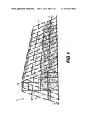
[0003] FIG. 1 is a view in Perspective of one fully assembled frame that may comprise plural end-to-end sections, end closures not being shown. The relative dimensions of the segment voids are formed by stamping of a wire platen. For rigidity, the voids are in rectangular confirmation.
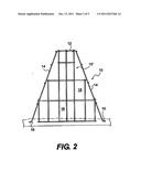
[0004] FIG. 2 depicts an End View of the invention, reference the garden ground line.
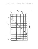
[0005] FIG. 3 shows a Top View of the roof and walls depending from the roof to the ground.
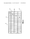
[0006] FIG. 4 shows a side view of a wall of the invention.
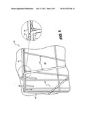
[0007] FIG. 5 is an enlarged view of the end closure or caps in partial section.
DESCRIPTION OF PREFERRED EMBODIMENTS
[0008] Referring to FIGS. 1, 2, 3, 4, and 5, the invention is illustrated in its broadest utility.
[0009] Galvanized metal frame 10 is initially formed by a press, prior to being defined on its exterior by segments 12, from which depend spaced apart walls 14. The roof, walls and closures 10' are segmented to allow the free flow of atmospheric elements: wind, rain, sun to pass to and fro the frame so as to enhance growth of the seedlings into mature plants, depending upon climatic conditions. In addition, Frame sections 10 form cavities or caps at each end of the frame, defining 10' segments therein end-to-end cavities 12'. Roof section 12 connects spaced apart walls 14. The frame itself is defined by galvanized metal wires of gauge 14. Cavity segments 12 are defined by the horizontal and vertical wires 12' which connected in rectangular configuration define rectangular cavities that open the roof, walls and capped ends of the frame all being open the atmosphere and the elements thereof. Rigid flanges 16 extend outwardly from the walls 14 to provide garden soil anchors for the entire frame. To sustain the frame in its rigid protective function the special fused wire configuration of connected voids is preferred.
[0010] While this invention has been described in conjunction with specific embodiments thereof, it is evident that many alternatives, modifications and variations will be apparent in those skilled in the art. Accordingly, the preferred embodiments of the invention, as set forth herein, are intended to be illustrative and not limiting. Various changes may be made without departing from the spirit and scope of the intention as defined in the following claims.
User Contributions:
Comment about this patent or add new information about this topic:
Images included with this patent application:
 |  |
 |  |
 |
| Similar patent applications: | |
| Date | Title |
|---|---|
| 2011-03-03 | Mini-greenhouse and plant protector |
| 2010-11-11 | Enhancing yields of harvested plant seeds by treating sowing seeds with selected doses of a physical plant stressor |
| 2011-10-13 | Control method and apparatus of wind machine for plant frost protection |
| 2009-02-05 | Garden or planter system with elevated bed and water reservoir |
| 2010-05-20 | Apparatus for shielding plants from adverse weather conditions |
| New patent applications in this class: | |
| Date | Title |
|---|---|
| 2016-09-01 | Sprayable non-woven fiber weed barrier |
| 2014-12-04 | Grass protector |
| 2014-05-15 | Container cover device, system, and method |
| 2013-05-16 | Covers for plant-growing media |
| 2011-11-03 | Pet toy |
| New patent applications from these inventors: | |
| Date | Title |
|---|---|
| 2014-03-27 | Garden plant protector |
| Top Inventors for class "Plant husbandry" | |
| Rank | Inventor's name |
|---|---|
| 1 | Donald E. Weder |
| 2 | Frank M. Stewart |
| 3 | Bruce G. Kania |
| 4 | Michael R. Klemme |
| 5 | David S. Mackenzie |