Patent application title: Support structure for stabilizing a container
Inventors:
Mike J. Ziegler (Kerrville, TX, US)
IPC8 Class: AB65D2500FI
USPC Class:
220737
Class name: Receptacles container attachment or adjunct container holder
Publication date: 2011-10-06
Patent application number: 20110240665
Abstract:
A structure for stabilizing a container includes a base having at least
one dimension greater than a horizontal dimension of the container. A
generally vertical member extends from the base in contact with the
container. An adjustable securing member engages the generally vertical
member and the container, and maintains contact between the container and
the generally vertical member to secure the container above the base,
such that the base retains the container in a generally upright
orientation. The container is thereby prevented from spilling and/or
falling when unintentionally provided with a lateral force or placed at
an angle with respect to a generally horizontal surface.Claims:
1. A structure for stabilizing a container having a horizontal dimension,
the structure comprising: a base having at least one dimension greater
than the horizontal dimension of the container; a generally vertical
member extending from the base and contacting the container; and an
adjustable securing member engaging the generally vertical member and the
container, wherein the adjustable securing member maintains contact
between the container and the generally vertical member for securing the
container above the base such that the base retains the container in a
generally upright orientation.
2. The structure of claim 1, wherein the base is generally circular, the base having a diameter greater than the horizontal dimension of the container.
3. The structure of claim 1, wherein the base comprises a weighted member for biasing the structure and the container toward the generally upright orientation.
4. The structure of claim 1, wherein the generally vertical member is secured to the base at a position offset from the center of the base such that the center of the container is generally disposed above and in alignment with the center of the base.
5. The structure of claim 1, wherein the generally vertical member comprises a first side and a second side angularly offset from the first side, and wherein the first side of the generally vertical member contacts a first portion of the container and the second side of the generally vertical member contacts a second portion of the container.
6. The structure of claim 5, wherein the first side is generally perpendicular to the second side.
7. The structure of claim 1, wherein the generally vertical member has a shape that defines a vertical space between the generally vertical member and the container for accommodating an elongate object.
8. The structure of claim 1, wherein the generally vertical member has a length less than a height of the container for facilitating access to an upper opening of the container.
9. The structure of claim 1, wherein the adjustable securing member comprises an elastic material for accommodating containers of varying size and retaining the container against the generally vertical member through application of tension to the container, the generally vertical member, or combinations thereof.
10. The structure of claim 1, wherein the adjustable securing member comprises at least one fastener for accommodating containers of varying size and retaining the container in a generally fixed position relative to the generally vertical member.
11. A method for stabilizing a container having a horizontal dimension, the method comprising the steps of: providing a structure comprising a base and a generally vertical member extending from the base, wherein the base has at least one dimension greater than the horizontal dimension of the container; placing a first portion of the container against the base and a second portion of the container against the generally vertical member; and engaging an adjustable securing member to the container and the generally vertical member, thereby securing the container to the structure, wherein the base retains the container in a generally upright orientation.
12. The method of claim 11, wherein the step of placing the first portion of the container against the base comprising placing the center of the container above and generally aligned with the center of the base.
13. The method of claim 11, wherein the step of placing the second portion of the container against the generally vertical member comprises placing a first side of the container against a first arm of the generally vertical member and a second side of the container against a second arm of the generally vertical member.
14. The method of claim 11, further comprising placing an elongate object within a space defined between the container and the generally vertical member.
15. The method of claim 11, wherein the step of engaging the adjustable securing member to the container and the generally vertical member comprises extending an enclosed loop of elastic material, placing the enclosed loop of elastic material around the container and the generally vertical member, and permitting the enclosed loop of elastic material to contract, wherein tension from the elastic material is applied to the container, the generally vertical member, or combinations thereof to secure the container to the structure.
16. The method of claim 11, wherein the step of engaging the adjustable securing member to the container and the generally vertical member comprises engaging at least one fastener of the adjustable securing member such that the adjustable securing member encloses the container and retains the container in a generally fixed position relative to the structure.
17. The method of claim 11, further comprising dispensing a material into or from an upper opening of the container while the container is secured to the structure.
18. The method of claim 11, further comprising placing the container and the structure on a generally horizontal surface, wherein the base retains the container in a generally upright orientation relative to the generally horizontal surface, biases the container toward the generally upright orientation, or combinations thereof.
Description:
FIELD
[0001] The present disclosure relates, generally, to a support structure usable to stabilize a bottle or similar type of container to prevent inadvertent tipping and/or falling of the container, and/or spillage of contents.
BACKGROUND
[0002] A typical bottle or other container usable to hold liquids, semi-solids, flowable solids, and similar contents is a generally elongate structure, having a height greater than the width of its base. As a result, the center of gravity of the container is positioned significantly above the base, especially when the container is full or mostly full. The relatively narrow base of the container generally does not support the container when the center of gravity is laterally displaced, such as when the container is inadvertently placed in a non-upright orientation or when a lateral force is unintentionally imparted to the container. For example, when such a container is used to pour or otherwise dispense its contents, then returned to a surface, it is common for the container to tip or wobble, and often fall. This can result in spillage of the contents of the container, breakage of the container, loss or undesired movement of the container, contact between the container and other objects that may in turn fall and/or spill their contents, and similar occurrences.
[0003] To reduce the likelihood of toppling and/or spilling, many containers are provided with a body having a significant width, or alternatively, a shape having a relatively broad base. However, broad or irregularly shaped containers occupy a greater quantity of storage space or workspace than typical bottles and containers, and such containers are often cumbersome or unwieldy to manipulate when dispensing contents. Various improvised methods also exist for enhancing the stability of containers. For example, numerous modeling hobbyists and artists utilize adhesive or other means to secure bottles of paint to wooden blocks, or similar broad structures, to effectively provide the bottles with a broad base that prevents toppling.
[0004] A need exists for a support structure usable to stabilize bottles and other containers that is simple in construction and use, inexpensive, lightweight, portable, and provides improved stabilization to a container over various crude, homemade, and/or improvised methods.
[0005] A need also exists for a support structure that is usable to accommodate containers having any shape or size.
[0006] A further need exists for a support structure that enables efficient access to and use of a secured container to dispense and/or receive contents while the container is secured.
[0007] Embodiments of the present invention meet these needs.
BRIEF DESCRIPTION OF THE DRAWINGS
[0008] In the detailed description of various embodiments of the present invention presented below, reference is made to the accompanying drawings, in which:
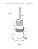
[0009] FIG. 1 depicts a front perspective view of an embodiment of a structure usable within the scope of the present disclosure.
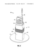
[0010] FIG. 2 depicts a back perspective view of the structure of FIG. 1.
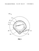
[0011] FIG. 3 depicts a top view of the structure of FIG. 1 and FIG. 2.
[0012] Embodiments of the present invention are described below with reference to the listed Figures.
DETAILED DESCRIPTION OF THE EMBODIMENTS
[0013] Before explaining selected embodiments of the present invention in detail, it is to be understood that the present invention is not limited to the particular embodiments described herein and that the present invention can be practiced or carried out in various ways.
[0014] The present disclosure relates, generally, to structures and methods usable to stabilize containers, such as bottles, cups, glasses, jars, jugs, or any other type of vessel or object usable to contain fluids, including, but not limited to liquids, semi-solids, and flowable solids. FIGS. 1 through 3 depict an embodiment of a structure (10) usable within the scope of the present disclosure. Specifically, FIG. 1 depicts a front perspective view of the structure (10) engaged with a container (18), FIG. 2 depicts a rear perspective view of the structure (10) and container (18), and FIG. 3 depicts a top view of the structure (10) and container (18).
[0015] The depicted structure (10) includes a base (12), a generally vertical member extending from the base (14), and an adjustable securing member (16) usable to engage the container (18) and the generally vertical member (14), to thereby secure the container (18) to the structure (10), such as through application of generally continuous tension to the container (18) and/or generally vertical member (14).
[0016] The base (12) is shown as a generally flat, circular member having a diameter greater than that of the container (18). It should be understood that while the base (12) is shown having a circular shape, the base (12) can readily be provided with another shape, including, without limitation, square, rectangular, triangular, oval, or elliptical shapes, or any other regular or irregular polygonal shape. Additionally, while FIGS. 1 through 3 depict the structure (10) engaged with a generally cylindrical container (18) having a constant diameter, it should be understood that embodiments of the present invention are usable to secure containers having any shape and/or dimensions. Generally, the base (12) can have at least one dimension longer than a selected horizontal dimension of the container (18), thereby providing the container (18) with an increased surface area usable to provide stability when placed against a generally horizontal surface.
[0017] In addition to increasing the surface area contacted by the container (18), in an embodiment of the invention, the base (12) can be weighted and/or can include a weighted member secured to the exterior of the base, or within a hollow portion of the base, to bias the structure (10) and container (18) toward a generally upright orientation, further stabilizing and preventing undesired toppling of and/or spillage from the container (18). For example, the base (12) can be formed from stainless steel, pewter, or a similar material, and can be weighted to bias the structure (10) toward an upright orientation, or alternatively, the base (12) can be formed from an at least partially hollow plastic member having a metallic or other weighted member disposed within.
[0018] The generally vertical member (14) can be integral with, welded to, or otherwise secured to the base (12), extending generally upward from the base (12) in contact with the container (18). While FIGS. 1 through 3 depict the generally vertical member (14) extending substantially vertically from and perpendicular to the base (12), other embodiments of the invention can include a generally vertical member (14) that extends from the base (12) at other angles. For example, an alternate angular relationship between the generally vertical member (14) and the base (12) can facilitate contact between the generally vertical member (14) and a container having an angled and/or arcuate exterior surface or shape. Additionally, while the generally vertical member (14) can be secured to, and/or integral with, any portion of the base, FIGS. 1 through 3 depict the generally vertical member (14) secured to the base (12) at a position offset from the center of the base (12), such that when the container (18) is secured to the structure (10), the center of the container (18) is disposed above and in alignment with the center of the base (12), thereby ensuring that the center of gravity of the container (18) remains generally central relative to the horizontal axes of the base (12).
[0019] While the generally vertical member (14) can be provided with any shape or configuration, in an embodiment of the invention, the generally vertical member (14) can have two or more sides and/or upright members, which can be integral with, secured to, or separated from one another, having an angular relationship therebetween such that a first side of the generally vertical member (14) contacts a first portion of the container (18), and a second side of the generally vertical member (14) contacts a second portion of the container (18), thereby bounding the container (18) on multiple sides to further enhance the stability thereof. For example, as depicted in FIGS. 1 through 3, the generally vertical member (14) can have two generally perpendicular sides (20, 22), providing the generally vertical member with an "L" shaped cross-section. The generally vertical member (14) thereby contacts the depicted container (18) at two points generally perpendicular from one another. While it should be understood that the generally vertical member (14) can be provided with any dimensions, FIGS. 1 through 3 depict an embodiment of the present invention in which the height of the generally vertical member (14) is less than that of the container (18), such that the lid, cap, and/or upper opening (24) of the container (18) is readily accessible and unimpeded by the generally vertical member (14).
[0020] In a further embodiment of the invention, the shape of the generally vertical member (14) and/or the shape of the exterior surface of the container (18) can define a space (26) between the container (18) and generally vertical member (14), which is usable to retain an elongate object (28). For example, FIGS. 1 through 3 depict the container (18) as a generally cylindrical bottle of modeling paint, which is secured against a generally "L" shaped generally vertical member (14) having two sides (20, 22). A space (26) is thereby defined adjacent to the right angle between the sides (20, 22) of the generally vertical member (14), which is usable to retain an elongate object (28) such as a paintbrush or similar utensil.
[0021] FIGS. 1 through 3 depict the adjustable securing member (16) as a generally elastic band and/or strap placed around the exterior of the container (18) and the generally vertical member (14) to thereby secure the container (18) against the interior surface(s) of the generally vertical member (14). For example, the depicted adjustable securing member (16) can include one or more bands and/or straps formed from rubber, nylon, or other generally elastic materials. Alternately, usable adjustable securing members can be integral with and/or attachable to the generally vertical member (14), such as adjustable belts having fasteners, clips, clasps, ratcheting systems, Velcro®, adhesives, or other fasteners usable to secure about the container (18). In use, the adjustable securing member can secure the container (18) by applying continuous tension to the container (18) and/or the generally vertical member (14). Use of an adjustable securing member enables containers having any shape or dimensions to be secured to the structure (10) in a manner that permits access to the lid and/or upper opening (24) of the container (18).
[0022] In use, the container (18) and structure (10) can be lifted from a surface, contents of the container (18) can be dispensed or the container (18) can be otherwise manipulated, and the container (18) and structure (10) can be returned to a generally horizontal surface. The base (12) of the structure (10) prevents toppling of the container (18) independent of the angle at which the container (18) is returned to the generally horizontal surface, and independent of any unintended lateral force imparted to the container (18) when returning the container (18) to the surface. When it is desirable to secure a differing container to the structure (10), the adjustable securing member (16) can be removed and/or released, and a second container can be secured to the structure (10) in a manner similar to the previous container.
[0023] While various embodiments of the present invention have been described with emphasis, it should be understood that within the scope of the appended claims, the present invention might be practiced other than as specifically described herein.
User Contributions:
Comment about this patent or add new information about this topic:
Images included with this patent application:
 |  |
 |
| Similar patent applications: | |
| Date | Title |
|---|---|
| 2011-07-07 | Closable aperture for retrofitting to a container |
| 2011-03-10 | Structure for tamper-resistance container |
| 2009-01-29 | Coated lift-tab for resealing pop-top containers |
| 2009-02-05 | Ergonomic system for handling a container |
| 2009-10-01 | Food plate with structure for accommodating fork tines |
| New patent applications in this class: | |
| Date | Title |
|---|---|
| 2017-08-17 | Device for allowing small cups to temporarily sit inside larger beer pong cups |
| 2016-07-07 | Liquid absorbing cupholder |
| 2016-07-07 | Cup holder |
| 2016-05-26 | Cup holder |
| 2016-04-21 | Liftable container holder |
| Top Inventors for class "Receptacles" | |
| Rank | Inventor's name |
|---|---|
| 1 | Daniel Lee Bizzell |
| 2 | Frank Yang |
| 3 | Terry Vovan |
| 4 | William P. Apps |
| 5 | Lowell L. Wood, Jr. |