Patent application title: HYDRAULIC ACCUMULATOR, IN PARTICULAR BELLOWS ACCUMULATOR
Inventors:
Herbert Baltes (Losheim, DE)
Herbert Baltes (Losheim, DE)
IPC8 Class: AF16L5504FI
USPC Class:
138 30
Class name: Pipes and tubular conduits with pressure compensators variable capacity chambers
Publication date: 2011-08-11
Patent application number: 20110192482
Abstract:
The invention relates to a hydraulic accumulator, in particular in the
form of a bellows accumulator, in which the bellows (13) which serves as
a movable separating element between a gas side (11) and a fluid side
(21) has, at that bellows end thereof which is movable in the axial
direction during expansion and contraction in the accumulator housing
which defines a longitudinal axis (9), a closure body (25) which closes
off the interior space (33) of the bellows (13) in a fluid-tight manner,
and in which the bellows, at the other bellows end (27) thereof, is
immovably fixed with respect to the accumulator housing (1), said
hydraulic accumulator being characterized in that the immovable bellows
end (27) is fixed to an end body (31) which is fixed with respect to the
housing, which end body (31) is in the form of a disk with a region (37)
which projects axially into the interior (33) of the bellows (13) from
the main plane (35) of the disk, and in that at least one fluid passage
(41, 43) is formed on the projecting region (37), which fluid passage
(41, 43) connects the interior space (33), which is associated with the
fluid side (21), of the bellows (13) to a fluid connection (17) of the
accumulator housing (1).Claims:
1. A hydraulic accumulator, in particular in the form of a bellows
accumulator, in which the bellows (13), which serves as a movable
separating element between a gas side (11) and a fluid side (21), has a
closure body (25), which closes off the interior space (33) of the
bellows (13) in a fluid-tight manner, on that bellows end that is capable
of moving in the axial direction during expansion and contraction in the
accumulator housing that defines a longitudinal axis (9); and the other
bellows end (27) of the bellows is secured so as to be immovable relative
to the accumulator housing (1), characterized in that the immovable
bellows end (27) is secured on an end body (31) that is rigidly mounted
in the housing and that has the form of a disk with a region (37) which
projects axially into the interior (33) of the bellows (13) from the main
plane (35) of the disk; and that the projecting region (37) has at least
one fluid passage (41, 43), which connects the interior space (33), which
is associated with the fluid side (21), of the bellows (13) to a fluid
connection (17) of the accumulator housing (1).
2. The hydraulic accumulator according to claim 1, characterized in that the projecting region in the interior (33) of the bellows (13) defines a central plane (37) that extends perpendicularly to the longitudinal axis (9).
3. The hydraulic accumulator according to claim 2, characterized in that the central plane (37) in relation to the longitudinal axis (9) is defined concentrically and at the edge by an inclined plane (39) sloping downward to the main plane (35), and that the fluid passages are passages (41) that are formed at least in the inclined plane (39) and that slope downward in the direction of the longitudinal axis (9).
4. The hydraulic accumulator according to claim 3, characterized in that, in addition to the downward sloping passages (41), there are axial passages (43) in the axially projecting region (37) of the end body (31) as the fluid passages.
5. The hydraulic accumulator according to claim 3, characterized in that the downward sloping passages (41) are arranged equidistant from each other on the inclined plane (39).
6. The hydraulic accumulator according to claim 4, characterized in that the axial passages (43) are arranged in circular rings (45, 47) that are concentric with the longitudinal axis (9) in the axially projecting region (37).
7. The hydraulic accumulator according to claim 2, characterized in that the region projecting into the interior (33) of the bellows (13) is connected to the central plane at the edge regions of the central plane (37) by means of connecting parts (61) that slope downward in the direction of the main plane (35), and that the fluid passages are formed by intermediate spaces (63) between the connecting parts (61).
8. The hydraulic accumulator according to claim 7, characterized in that the central plane (37) has a square shape and that each corner (65) of the square has a connecting part (61).
9. The hydraulic accumulator according to claim 1, characterized in that the accumulator housing (1) has a cup-like, hollow cylindrical main part (3) and a housing closure part (15), which closes the opening of the cup and which is welded to the main part (3) along a weld line (16), and that the end body (31) of the bellows (13) is secured on the periphery of the accumulator housing (1) in the region of the weld line (16).
10. The hydraulic accumulator according to claim 1, characterized in that the side of the end body (31) opposite the projecting region (37) forms an annular area (49) that extends into a radial plane and that surrounds a depression (51) that is concentric with the axis (9) and that is defined by the wall of the axially projecting region (37).
11. The hydraulic accumulator according to claim 10, characterized in that the annular area (49) of the end body (31) surrounds the coaxial fluid connection (17) in the housing closure part (15) that is in alignment with the radially inner edge of the annular area (49) and the entrance of the depression (51).
12. The hydraulic accumulator according to claim 1, characterized by a metal bellows (13), which is welded to the metal closure body (25) on one bellows end (23) and to the metal end body (31) on the other bellows end (27).
Description:
[0001] The invention relates to a hydraulic accumulator, in particular in
the form of a bellows accumulator, in which the bellows, which serves as
a movable separating element between a gas side and a fluid side, has a
closure body, which closes off the interior space of the bellows in a
fluid-tight manner on that end of the bellows that is capable of moving
in the axial direction during expansion and contraction in the
accumulator housing that defines a longitudinal axis; and the other
bellows end of the bellows is secured so as to be immovable relative to
the accumulator housing.
[0002] Hydraulic accumulators comprising a bellows that serves as an immovable separating element are known and used in a plurality of technical fields, for example, in hydraulic brake systems for vehicles and in various kinds of industrial hydraulic systems. EP 1 052 412 A2, for example, discloses a bellows accumulator with a metal bellows that serves as a movable separating element between a gas side and a fluid side.
[0003] In hydraulic accumulators of this type, the bellows represents, as the element with the highest stress, the component that is critical to operational safety. While the risk of damage is rather low when the bellows is extended so that the folds of the bellows that have approached one another are moved away from each other, compressive strain may occur when the bellows are completely contracted so that the adjacent folds of the bellows are compressed. Such a risk exists especially if total contraction of the bellows occurs suddenly in operation.
[0004] In light of this problem, the object of the invention is to provide a hydraulic accumulator in the form of a bellows accumulator that effectively avoids the risk of the bellows being damaged in operation.
[0005] The object of the invention is achieved by a hydraulic accumulator that has the features disclosed in patent claim 1 in its entirety.
[0006] Accordingly, an essential feature of the invention consists in the immovable end of the bellows having an end body that forms not only the fluid connection between the interior space of the bellows that is associated with the fluid side and a fluid connection of the accumulator housing, but this end body also has a region that projects axially into the interior of the bellows. In this way, the end body with its projecting region can form, as an additional function, an end or safety stop for the closure body of the movable bellows end and comes to rest against the projecting region during contraction of the bellows, when the axial height of the elevation is chosen in such a way that the closure body of the movable end of the bellows end comes to rest against the projecting region of the end body during contraction before the adjacent folds of the bellows are compressed with one another. As a result, increased operational safety is achieved in long term operation.
[0007] In especially advantageous embodiments, the projecting region in the interior of the bellows defines a central plane that extends perpendicularly to the longitudinal axis. The result of this arrangement is a flat safety stop with a large surface, against which the closure body can rest so as to be tilt proof.
[0008] In especially advantageous embodiments, the arrangement is configured in such a way that the central plane in relation to the longitudinal axis is defined concentrically and at the edge by an inclined plane sloping downward to the main plane, wherein the fluid passages are passages that are formed at least in the inclined plane and that slope downward in the direction of the longitudinal axis. This configuration of the fluid passages offers the additional advantage that these passages may serve as the flushing ports, because they run into the bellows interior at the slope between the projecting central part and the bellows interior. During contraction of the bellows, the dirt particles that may have collected in the annular space between the inclined plane and the bellows interior are flushed out of the flushing ports.
[0009] However, it may be advantageous to have, in addition to the downward sloping passages, additional axial passages in the axially projecting region of the end body as the fluid passages, as a result of which the flow cross section between the interior space of the bellows and the fluid connection of the accumulator housing is significantly enlarged.
[0010] It is advantageous to arrange the downward sloping passages equidistant from each other on the inclined plane; and the axial passages can be arranged in circular rings that are concentric with the longitudinal axis in the axially projecting region.
[0011] As an alternative, the arrangement can be configured with respect to the formation of the fluid passages in such a way that the region projecting into the interior of the bellows is connected to the central plane at the edge regions of the central plane by means of connecting parts that slope downward in the direction of the main plane, the fluid passages being formed by intermediate spaces between the connecting parts. In contrast to the formation of the fluid passages by means of downward sloping passages, for example, by introducing oblique drill holes, the exemplary embodiments in which the central plane is connected to the other part of the interior body only at individual edge regions, are characterized by their extreme ease of production and, thus, low manufacturing costs.
[0012] The pertinent arrangement can be configured in such a way that the central plane has a square shape and that each corner of the square has a connecting part.
[0013] In preferred embodiments, the accumulator housing has a cup-like, hollow cylindrical main part and a housing closure part, which closes the opening of the cup and which is welded to the main part along a weld line, the end body of the bellows being secured on the periphery of the accumulator housing in the region of the weld line. This feature permits an efficient production process in that both the end body is secured and also the accumulator housing is closed in one combined welding step.
[0014] The side of the end body opposite the projecting region can form an annular area that extends into a radial plane and that surrounds a depression that is concentric with the axis and that is defined by the wall of the axially projecting region.
[0015] If, in this case, the annular area of the end body surrounds the coaxial fluid connection in the housing closure part that is in alignment with the radially inner edge of the annular area and the entrance of the depression, the result is advantageously an uninterrupted flow path from the exterior of the accumulator housing to the fluid passages in the end body.
[0016] The invention is explained in detail below by means of the embodiments depicted in the drawings.
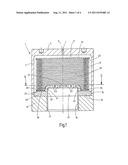
[0017] FIG. 1 is a schematically simplified longitudinal view, drawn approximately in natural size, of a practical configuration of an exemplary embodiment of the hydraulic accumulator according to the invention;
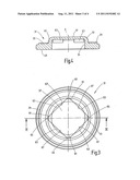
[0018] FIG. 2 is a top view of just one end body of the bellows of the exemplary embodiment that is shown in FIG. 1 and that is seen in the viewing direction indicated with the numerals II-II in FIG. 1;
[0019] FIG. 3 is a top view that corresponds to the view in FIG. 2 of an end body according to a modified exemplary embodiment;
[0020] FIG. 4 is a sectional view of the end body of FIG. 3, corresponding to the cutting line, marked with the numerals IV-IV in FIG. 3; and
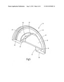
[0021] FIG. 5 is a perspective oblique view of the end body from FIGS. 3 and 4, cut open approximately in half.
[0022] In the drawing, the invention is described by means of one exemplary embodiment in the form of a pulsation damper. An accumulator housing, designated as a whole as 1, has a housing main part 3 in the form of a circular cylindrical cup with an end 5 that is located at the top in the drawing and that is closed except for a charging port 7, which is in alignment with the longitudinal axis 9 of the housing. In the drawing of FIG. 1, the charging port 7 is still open; that is, the gas side 11, which borders on the charging port 7 and which is located on the outside of a metal bellows 13, has not yet been filled with a working gas. The housing 1 is closed by a housing closure part 15 on the end that is located at the bottom in FIG. 1 and is opposite the charging port 7. This housing closure part is sealingly welded to the housing main part 3 along a weld line 16. In the closure part 15, a fluid inlet 17, which is concentric with the axis 9 and has an inside thread 19 for a fluid connection, is concentric with the axis 9.
[0023] In the interior of the accumulator housing 1, a metal bellows 13 forms a movable separating element between the gas side 11 and the fluid side 21, bordering on the fluid inlet 17. A closure body 25 closes off the metal bellows 13 in a fluid-tight manner at its bellows end 23 that is located at the top. This closure body is formed by a flat, thin metal plate that is welded to the last bellows fold at the bellows end 23. The other bellows end 27, the immovable bellows end, located at the bottom in FIG. 1, is welded with the bottommost bellows fold in a fluid-tight manner to a weld region 29 on a metallic end body 31, which in turn is welded to the accumulator housing 1 along the weld line 16 between the housing main part 3 and the housing closure part 15.
[0024] As stated, in the state depicted in FIG. 1, the gas side 11 has not been provided yet with a working gas under a pre-charge pressure, so that the bellows 13 is in the extended state, where the closure body 25 is in proximity to the upper end 5 of the accumulator housing 1. When the pressure prevails on the gas side 11, a fill with the working gas, such as N2, and alternating fluid pressure on the fluid side 21 cause the closure body 25 to move axially. When the hydraulic accumulator is used as a pulsation damper, in the course of which the fluid side 21 is in fluid connection with a compressed fluid, in particular a hydraulic fluid, a fuel, or lubricant by way of the fluid inlet 17, in order to smooth any pressure surges that might occur, it has been proven to be advantageous for the gas side 11 to have not only a fill with the working gas, but also to have a predefined fraction of a fluid. In this case, a combination of nitrogen gas as the working gas and ethyl alcohol as the fluid on the gas side 11 of the accumulator has been proven to be especially advantageous as the fill. In operation, the fluid between the folds and deflections of the bellows 13 can form a damping support medium, which can support, as the back support, the folded wall sections of the bellows 13 on the fluid, as a result of which the service life of the bellows 13 is extended; and, consequently, the functional reliability is increased. This aspect applies especially to sudden pulsations and rapid pressure surges.
[0025] The end body 31, which is provided on the immovable bellows end 27, forms fluid passages as a connection between the interior space 33 of the bellows 13 associated with the fluid side 21 and the fluid inlet. The end body 31 has the form of a round disk that defines a plurality of radial planes, that is, an outer plane 35, which is referred to herein as the main plane and which borders on the peripheral edge, and a plane 37, which is centrally located in relation to the longitudinal axis 9 and which forms a region which projects axially into the interior space 33 of the bellows 13, on the end body 31. The plane 35, which is referred to herein as the main plane, is located at the edge of the weld region 29, which projects slightly beyond this plane 35 and at which the immovable bellows end 27 is secured.
[0026] The central plane 37, which forms the projecting region, is defined at the edge by an inclined plane 39. The inclined plane 39 has oblique drill holes 41, which slope downward in the direction of the longitudinal axis 9 and are arranged so as to be uniformly distributed around the periphery of the inclined plane 39. The oblique drill holes form a first group of fluid passages between the fluid inlet 17 and the interior space 33 of the bellows 13. A second group of fluid passages is constructed in the form of axial drill holes 43 in the projecting region defined by the central plane 37. As shown in FIG. 2, the axial drill holes 43 are arranged so as to be uniformly distributed along two concentric circular lines 45 and 47.
[0027] The side of the end body 31 that is opposite the planes 37 and 35 forms an annular area 49 which extends into a radial plane in the end body 31. This annular area surrounds a depression 51, which is concentric with the axis 9 and which is formed by the inner wall of the region, which projects into the interior space 33 of the bellows 13 and which is defined by the central plane 37. In the present exemplary embodiment, the radial inner edge of the annular area 49 and, with it, the opening edge of the depression 51 for opening the fluid inlet 17 are in alignment, so that an uninterrupted flow path from the fluid inlet 17 into the depression 51 of the end body 31 is formed. The fluid passages formed in the end body 31, that is, the oblique drill holes 41 in the inclined plane 39 as well as the axial drill holes 43 in the projecting region, continue the flow path into the interior space 33.
[0028] The plane 37 of the projecting region is offset axially in relation to the main plane designated as 35 by such a distance in the interior space 33 that the plane 37 forms an end stop against which the closure body 25 rests at the movable bellows end 23 when the bellows 13 is totally contracted. The passages, formed by the oblique drill holes 41, remain open as the fluid passages, even if, when the bellows 13 is totally contracted, the closure body 25 rests flush on the plane 37 and closes the axial drill holes 43. Even while the end body 31 exercises its safety or stop function, the interior space 33 of the bellows 13 remains, therefore, with the remaining residual fluid volume connected to the fluid inlet 17. Owing to the arrangement of the oblique drill holes 41, which run into the inclined plane 39, these oblique drill holes 41 serve additionally as flushing ports, through which the dirt particles, which have accumulated at the immovable bellows end 27 in the region between the inclined plane 39 and the bellows interior, are flushed out during the axial movements, which the closure body 25 carries out in operation during contraction of the bellows 13. As stated above, the distance by which the plane 37 projects axially in relation to the immovable bellows end 27 is chosen in such a way that when the closure body 25 rests against the plane 37, the folds of the bellows 13 are not pressed against each other. The pertinent arrangement can be configured in such a way that a desired residual volume of fluid remains in the interior space 33 of the bellows 13.
[0029] FIGS. 3 to 5 depict a second exemplary embodiment, in which an end body 31 is provided in a simplified type of construction. The end body 31 of this exemplary embodiment differs from the above-described first embodiment only in the design of the region projecting into the interior 33 of the bellows 13. As in the first example, this projecting region is also formed by a plane 37, which runs perpendicular to the longitudinal axis 9 as the safety end stop for the closure body 25 of the bellows 13. In contrast to the first described example, the plane 37 is square in contour, but each of the corner regions has a connecting part 61, which slopes downward to the main plane 35 in a curved inclined course, so that an intermediate space 63 is formed between each of the adjacent corners 65. This intermediate space extends along a straight side 67 of the square, so that a fluid passage is formed on each square side 67 from the edge of the square to the opening of the depression 51. As can be seen from the drawing, this embodiment does not provide that the plane 37 has additional axial drill holes as the fluid passages. The size of the fluid passages that are formed by the intermediate spaces 63 causes the flow resistance to be low even without additional axial drill holes.
[0030] The end body 31 in the second type of construction is easy to manufacture in that in the end bodies in the form of the end body 31 from FIGS. 1 and 2 that are shaped by forming or machining processes, instead of introducing the drill holes 41 and 43 at the projecting region, straight cut outs are made. These straight cut outs run along the sides 67 and form the square shape of the plane 37 while simultaneously producing the intermediate spaces 63 as the fluid passages.
User Contributions:
Comment about this patent or add new information about this topic:
Images included with this patent application:
 |  |
 |  |
| New patent applications in this class: | |
| Date | Title |
|---|---|
| 2017-08-17 | Bicycle hydraulic hose cap and bicycle hydraulic hose assembly |
| 2016-04-28 | Tubular occlusion and pressure damping system and temporal pressure controlling arrangement |
| 2016-02-25 | Accumulator |
| 2016-01-28 | Accumulator membrane for a hydraulic hammer |
| 2015-11-26 | Metallic liner pressure vessel comprising polar boss |
| New patent applications from these inventors: | |
| Date | Title |
|---|---|
| 2016-11-17 | Accumulator device |
| 2016-11-17 | Hydraulic accumulator |
| 2015-11-12 | Separating device for fluid media |
| 2014-10-23 | Pressure accumulator |
| 2014-10-09 | Pressure accumulator |
| Top Inventors for class "Pipes and tubular conduits" | |
| Rank | Inventor's name |
|---|---|
| 1 | Larry W. Kiest, Jr. |
| 2 | Kristian Glejbol |
| 3 | Geoffrey Stephen Graham |
| 4 | Frederick W. Zeyfang |
| 5 | Kenji Fujii |