Patent application title: RETAINING APPARATUS FOR DATA STORAGE DEVICE
Inventors:
Zhan-Yang Li (Shenzhen City, CN)
Assignees:
HONG FU JIN PRECISION INDUSTRY (ShenZhen) CO., LTD.
HON HAI PRECISION INDUSTRY CO., LTD.
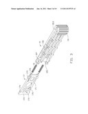
IPC8 Class: AA47B9600FI
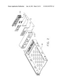
USPC Class:
211 262
Class name: Special article electrically powered supporting part of an article
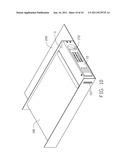
Publication date: 2011-06-16
Patent application number: 20110139735
Abstract:
A retaining apparatus includes a tray and a retaining member. The tray is
used for receiving at least one data storage device. The retaining device
includes a base member, a retaining member, an arm member and a locking
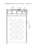
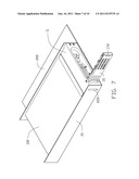
member. The base member is attached to the tray. The retaining member is
movably attached to the base member along a first direction. The
retaining member includes an engaging portion, a retaining portion and a
latch. The arm member is pivotably attached to the base member about a
pivot axis, and the pivot axis is located at a first end of the arm
member. The locking member is slidably attached to the arm member. The
arm member includes a latching portion.Claims:
1. A retaining apparatus comprising: a tray for receiving at least one
data storage device; and a retaining device comprising: a base member
attached to the tray; a retaining member movably attached to the base
member along a first direction, the retaining member comprising an
engaging portion, a retaining portion and a latch; an arm member
pivotably attached to the base member about a pivot axis, the pivot axis
being located at a first end of the arm member; the arm member comprising
a driving portion at the first end engaged with the engaging portion;
wherein the first direction is substantially perpendicular to the pivot
axis; the retaining member is capable of being driven to move along the
first direction by rotating the arm member; and a locking member slidably
attached to the arm member, the arm member comprising a latching portion;
wherein the arm member is capable of being moved relative to the base
member from a latched state, where the latch is engaged with the latching
portion, to a unlatched state, where that the locking member is
disengaged from the latching portion; wherein the arm member is rotatable
between a retaining position where the arm member is positioned parallel
to the base member, and the retaining portion is driven to protrude out
of the base member, and a releasing position where the arm member is
angled from the base member, and the retaining portion resides in the
base member.
2. The retaining apparatus of the claim 1, wherein the engaging portion comprises a plurality of engaging teeth; and the driving portion has a plurality of driving teeth that mesh with the plurality of engaging teeth.
3. The retaining apparatus of the claim 1, wherein the arm member defines a receiving space for receiving the locking member.
4. The retaining apparatus of the claim 1, wherein the arm member comprises a main body and defines an opening for receiving the latch, the latching portion protrudes from the main body, and the opening is defined adjacent to the latching portion.
5. The retaining apparatus of the claim 4, wherein the latching portion partly covers the opening.
6. The retaining apparatus of the claim 4, wherein at least one resilient catch is formed on the main body, and at least one block is formed on the arm member corresponding to the at least one resilient catch.
7. The retaining apparatus of the claim 6, wherein the main body has a plate like configuration, and the at least one resilient catch and the main body are located on a same plane.
8. The retaining apparatus of the claim 1, wherein at least one elastic element is located between the locking member and the arm member.
9. The retaining apparatus of the claim 1, wherein the locking member has an end portion, and the end portion extends from a free end of the arm member.
10. An electronic device comprising: a bracket comprising a side plate, the side plate comprising a retaining opening at a front end thereof; and a retaining apparatus comprising: a tray for receiving a data storage device; and a retaining device comprising: a base member attached to the tray; a retaining member movably attached to the base member along a first direction, the retaining member comprising an engaging portion, a retaining portion and a latch; an arm member pivotably attached to the base member about a pivot axis, the pivot axis being located at a first end of the arm member; the arm member comprising a driving portion at the first end engaged with the engaging portion; wherein the first direction is substantially perpendicular to the pivot axis; the retaining member is capable of being driven to move along the first direction by rotating the arm member; and a locking member slidably attached to the arm member, the arm member comprising a latching portion; wherein the arm member is capable of being moved relative to the base member from a latched state, where the latch is engaged with the latching portion, to a unlatched state, where the locking member is disengaged from the latching portion; wherein the arm member is rotatable between a retaining position where the arm member is positioned parallel to the base member, and the retaining portion is driven to protrude out of the base member to engage with the side plate at the retaining opening, and a releasing position where the arm member is angled from the base member, and the retaining portion resides in the base member and is disengaged from the side plate.
11. The electronic device of the claim 10, wherein the engaging portion comprises a plurality of engaging teeth; and the driving portion has a plurality of driving teeth that mesh with the plurality of engaging teeth.
12. The electronic device of the claim 10, wherein the arm member defines a receiving space for receiving the locking member.
13. The electronic device of the claim 10, wherein the arm member comprises a main body and defines an opening for receiving the latch, the latching portion protrudes from the main body, and the opening is defined adjacent to the latching portion.
14. The electronic device of the claim 13, wherein the latching portion partly covers the opening.
15. The electronic device of the claim 13, wherein at least one resilient catch is formed on the main body, and at least one block is formed on the arm member corresponding the at least one resilient catch.
16. The electronic device of the claim 15, wherein the main body has a plate like configuration, and the at least one resilient catch and the main body are located on a same plane.
17. The electronic device of the claim 15, wherein at least one elastic element is located between the locking member and the arm member.
18. The electronic device of the claim 10, wherein the locking member has an end portion, and the end portion extends from a free end of the arm member.
Description:
CROSS-REFERENCE TO RELATED APPLICATION
[0001] This application is related to co-pending U.S. patent application entitled "RETAINING APPARATUS FOR DATA STORAGE DEVICES", application Ser. No. 12/534,215, Application date Aug. 3, 2009, Attorney Docket number US25378.
BACKGROUND
[0002] 1. Technical Field
[0003] The disclosure generally relates to a retaining apparatus for data storage devices, especially to a retaining apparatus with a tray for receiving and retaining at least one data storage device.
[0004] 2. Description of Related Art
[0005] Typically, a data storage device, such as a hard disk drive is simply screwed to a computer enclosure. This conventional mounting means can be complex, difficult and substantially wastes time. In addition, in use, vibration of the data storage device may cause the screws to come loose and may result in damage to the data storage device. Understandably, some attempts have been taken to introduce a mounting apparatus for a data storage device without screws.
BRIEF DESCRIPTION OF THE DRAWINGS
[0006] FIG. 1 is an exploded, isometric view of a retaining apparatus according to an embodiment.
[0007] FIG. 2 is similar to FIG. 1, but shown in another aspect.
[0008] FIG. 3 is enlarged view of an arm member, a locking member and coin springs of FIG. 1.
[0009] FIG. 4 is an assembled view of FIG. 3.
[0010] FIG. 5 is an assembled view of FIG. 1 with an arm member positioned oblique to a base member.
[0011] FIG. 6 is a sectional view of FIG. 5.
[0012] FIG. 7 is an assembled view of a data storage device, a retaining apparatus and a bracket.
[0013] FIG. 8 is similar to FIG. 5, but showing the arm member positioned parallel to the base member.
[0014] FIG. 9 is a sectional view of FIG. 8.
[0015] FIG. 10 is similar to FIG. 7, but showing the retaining apparatus mounted to the bracket.
DETAILED DESCRIPTION
[0016] Referring to FIG. 7, a bracket 200 is used in a computer or an electronic device for mounting at least one retaining apparatus for data storage device 100. The bracket 200 includes two parallel side plates 21. A slideway is defined between the two side plates 21 for receiving the retaining apparatus. One of the side plates 21 defines a rectangular retaining opening 220.
[0017] Referring to FIG. 1 and FIG. 2, each retaining apparatus includes a tray 30 and a retaining device 10.
[0018] The retaining device 10 includes a base member 11, a retaining member 13, an arm member 15, and a locking member 17.
[0019] The base member 11 defines a pair of pivot holes 1132 at one end thereof. A pivot shaft 19 extends through the two pivot holes 1132 to define a pivot axis. The base member 11 includes a top wall 112, a bottom wall 113, and two opposite sidewalls 117. The top wall 112, the bottom wall 113 and the sidewalls 117 are enclosed to from a cavity 111 to receive the retaining member 13, the arm member 15, and the locking member 17. A channel 1173 is defined at one of the sidewall 117 of the base member 11. A latch 116 protrudes from the base member 11 in the cavity 115.
[0020] The retaining member 13 is movably attached to the base member 11 along a first direction. The retaining member 13 includes an engaging portion 137 and a retaining portion 135. The engaging portion 137 includes a plurality of engaging teeth.
[0021] Referring to FIG. 3, the locking member 17 includes a main body 171, an end portion 172, a latching portion 176 protruding from the main body 171, two restricting tabs 174, two resilient catches 175 and two posts 178. The main body 171 has a plate like configuration. The catches 175 are placed at two opposite side of the main body 171. The catches 175 and the main body 171 are positioned on a same plane. An opening 173 is defined in the main body 171 adjacent to the latching portion 176. The latching portion 176 partly covers the opening 173 so that the latch 116 can move into the portion of the opening 173 and engage with the latching portion 176.
[0022] The arm member 15 defines a pivot hole 1513 corresponding to the pivot shaft 12 and has a driving portion 151 corresponding to the engaging portion 137. The driving portion 151 has a plurality of driving teeth to mesh with the engaging teeth of the engaging portion 137. The arm member 15 defines a receiving space 155 for receiving the locking member 17. Two first blocks 157 and two second blocks 158 are formed on the arm member 15 and correspond to the restricting tabs 174 and the catches 175. The first blocks 157 can restrict movement of the locking member 17 to prevent movement into the arm member 15.
[0023] Referring to FIG. 4, when assembling the locking member 17 to the arm member 15, the locking member 17 is moved into the receiving space 155 of the arm member 15. Two coil springs 16 are located between the locking member 17 and the arm member 15. The coil springs 16 are compressed and provide ejection force to move the locking member 17 away from the arm member 15. The catches 175 are hooked on the second blocks 158 for holding the locking member 17 in the arm member 15. The end portion 172 extends from a free end of the arm member 15.
[0024] Referring through FIG. 5 to FIG. 6, when assembling the retaining apparatus, the base member 11 is mounted to the tray 30. The retaining member 13 is moved into the cavity 111 of the base member 11. The arm member 15 is pivotably fixed to the base member 11 about the pivot axis, and the driving portion 151 meshes with the engaging portion 137. The arm member 15 then is rotated relative to the retaining member 13 so that the retaining portion 135 resides in the cavity 111 of the base member 11.
[0025] Referring to FIG. 7 and FIG. 10, when mounting the retaining apparatus into the bracket 200, the tray 30 and the retaining device 10 are completely slid into the slideway of the bracket 200 with the channel 1173 aligned with the retaining opening 220. Then the arm member 15 is urged to rotate toward the base member 11, and drives the retaining portion 135 to move out of the channel 1173 to engage with the side plate 21 at the retaining opening 220. When the free end of the arm member 15 reaches the base member 11, the latch 116 moves into the opening 173 and engages with the latching portion 176 of the locking member 17. The retaining apparatus is thus mounted to the bracket 100.
[0026] When removing the retaining apparatus from the bracket 100, the locking member 17 is pressed on the end portion 172. The latch 116 is disengaged from the latching portion 176. Then, the arm member 15 is rotated outwardly from the base member 11. The retaining portion 135 moves into the cavity 111 of the base member 11 and disengages from the side plate 21 of the bracket 200. The retaining apparatus then is capable of being moved out of the bracket 200.
[0027] It is to be understood, however, that even though numerous characteristics and advantages have been set forth in the foregoing description of preferred embodiments, together with details of the structures and functions of the preferred embodiments, the disclosure is illustrative only, and changes may be made in detail, especially in matters of shape, size, and arrangement of parts within the principles of the invention to the full extent indicated by the broad general meaning of the terms in which the appended claims are expressed.
User Contributions:
Comment about this patent or add new information about this topic:
| People who visited this patent also read: | |
| Patent application number | Title |
|---|---|
| 20170016887 | ENHANCEMENT SOLUTION FOR ENHANCING CHEMILUMINESCENCE AND METHOD FOR PREPARING CHEMILUMINESCENT SOLUTION |
| 20170016886 | INDUCED PLURIPOTENT STEM CELL MODEL OF NOONAN SYNDROME AND USE THEREOF |
| 20170016885 | COMPOSITIONS AND METHODS FOR MEASURING CELLULAR MECHANICAL STRESS |
| 20170016884 | A NOVEL, HIGH-THROUGHPUT, NANOTOPOGRAPHIC PLATFORM FOR SCREENING CELL MIGRATORY BEHAVIOR |
| 20170016883 | Methods for monitoring physiological status of a body organ |
Images included with this patent application:
 |  |
 |  |
 |  |
 |  |
 |  |
| Similar patent applications: | |
| Date | Title |
|---|---|
| 2010-12-09 | Retaining apparatus for data storage device |
| 2012-02-16 | Shock prevention apparatus of medium cassette and financial device |
| 2010-01-14 | Reinforcing frame structure for a storage rack |
| 2011-09-22 | Mounting apparatus for electronic device |
| 2009-01-29 | Can receiving apparatus and refrigerator having the same |
| New patent applications in this class: | |
| Date | Title |
|---|---|
| 2016-06-16 | Mounting fixture system |
| 2015-01-29 | Release latch |
| 2014-09-18 | Gondola shelf wire routing tray |
| 2014-08-28 | Distribution panel with dual movable trays |
| 2014-06-26 | Storage and charging station system for portable electronic devices |
| New patent applications from these inventors: | |
| Date | Title |
|---|---|
| 2014-01-09 | Mounting apparatus for fan module |
| 2013-07-04 | Mounting apparatus for fan module |
| 2013-07-04 | Mounting apparatus for power supply |
| 2013-07-04 | Mounting apparatus for circuit board |
| 2013-06-27 | Mounting apparatus for circuit board |
| Top Inventors for class "Supports: racks" | |
| Rank | Inventor's name |
|---|---|
| 1 | Stephen N. Hardy |
| 2 | Wen-Tsan Wang |
| 3 | Gregory M. Bird |
| 4 | Shane Obitts |
| 5 | Kaveh Didehvar |