Patent application title: Transmission power control method and system for a physical uplink shared channel
Inventors:
Bo Dai (Shenzhen, CN)
Peng Hao (Shenzhen, CN)
Zhisong Zuo (Shenzhen, CN)
Zhisong Zuo (Shenzhen, CN)
Guanghui Yu (Shenzhen, CN)
Guanghui Yu (Shenzhen, CN)
Jin Xu (Shenzhen, CN)
Jin Xu (Shenzhen, CN)
Assignees:
ZTE CORPORATION
IPC8 Class: AH04W5204FI
USPC Class:
455522
Class name: Central station (e.g., master, etc.) to or from mobile station transmission power control technique
Publication date: 2011-03-10
Patent application number: 20110059764
Inventors list |
Agents list |
Assignees list |
List by place |
Classification tree browser |
Top 100 Inventors |
Top 100 Agents |
Top 100 Assignees |
Usenet FAQ Index |
Documents |
Other FAQs |
Patent application title: Transmission power control method and system for a physical uplink shared channel
Inventors:
Peng Hao
Jin Xu
Bo Dai
Guanghui Yu
Zhisong Zuo
Agents:
Assignees:
Origin: ,
IPC8 Class: AH04W5204FI
USPC Class:
Publication date: 03/10/2011
Patent application number: 20110059764
Abstract:
The present disclosure provides a transmission power control method for a
physical uplink shared channel, including: when there is only uplink
control information but no uplink shared channel data sent over the
physical uplink shared channel, the transmission power of the physical
uplink shared channel is set according to the total number of bits
contained in a channel quality indication signaling and its corresponding
cyclic redundancy check as well as an amplitude offset. The present
disclosure also provides a transmission power control system for a
physical uplink shared channel. The method and system described in the
present disclosure can ensure the overall performance of a system.Claims:
1. A transmission power control method for a physical uplink shared
channel, including: when there is only uplink control information but no
uplink shared channel data sent over the physical uplink shared channel,
setting the transmission power of the physical uplink shared channel
according to the total number of bits contained in a channel quality
indication signaling and its corresponding cyclic redundancy check as
well as an amplitude offset.
2. The method according to claim 1, wherein the transmission power of the physical uplink shared channel is set according to the following formula:PPUSCH(i)=min{PMAX,10log10(MPUSCH(i)+PO.- sub.--.sub.PUSCH(j)+αPL+ΔTF(i)+f(i)},where PMAX represents an upper limit of transmission power;MPUSCH(i) represents bandwidth used for transmitting the physical uplink shared channel in subframe i;PO.sub.--.sub.PUSCH(j) represents target reference power;α represents a path loss correction factor;PL represents path loss;f(i) represents a power control correction function of subframe i;ΔTF(i) is a transmission format offset parameter;when KS=1.25, ΔTF(i)=10log10((2.sup.MPRKS-1)Δβ) or ΔTF(i)=10log10(2.sup.MPRKS-1)+Δβ;when KS=0, ΔTF(i)=0;wherein KS is a parameter configured by radio resource control at a high layer;wherein MPR=O/NRE, where NRE represents the number of resource elements, NRE=MPUSCHNscRBNsymbPUSCH, where MPUSCH represents the bandwidth used for transmitting the physical uplink shared channel, NsymbPUSCH represents the number of single carrier-frequency division multiple access symbols used for transmitting the PUSCH, NscRB represents the number of resource elements contained in a resource block, O represents the size of information bits, and Δβ represents the amplitude offset;wherein when there is only uplink control information but no uplink shared channel data sent over the physical uplink shared channel, O=OCQI, and when ΔTF(i)=10log10((2.sup.MPRKS-1)Δβ), Δβ=βoffsetCQI, or when ΔTF(i)=10log10(2.sup.MPRKS-1)+Δβ, Δβ=10log10 βoffsetCQI, where OCQI represents the total number of bits contained in the channel quality indication signaling and its corresponding cyclic redundancy check, βoffsetCQI represents an amplitude offset of channel quality indication information, and MPUSCH is obtained according to a signaling in an initial PDCCH of a transmission block.
3. The method according to claim 2, wherein the βoffsetCQI is notified by a high layer signaling.
4. The method according to claim 2, wherein the value of the βoffsetCQI is 0.750, 1.000, 1.125, 1.250, 1.375, 1.625, 1.750, 2.000, 2.250, 2.500, 2.875, 3.125, 3.500, 4.000, 5.000 or 6.250.
5. The method according to claim 2, wherein when there is only uplink shared channel data sent over the physical uplink shared channel, or when there are both uplink control information and uplink shared channel data sent over the physical uplink shared channel, O=TBS, when ΔTF(i)=10log10((2.sup.MPRKS-1)Δβ), Δβ=1, or when ΔTF(i)=10log10(2.sup.MPRKS-1)+Δβ, Δβ=0, where TBS represents the size of a transmission block, and TBS and MPUSCH are obtained according to the signaling in the initial PDCCH of the transmission block.
6. The method according to claim 2, wherein when there is only uplink shared channel data sent over the physical uplink shared channel, O=TBS, when ΔTF(i)=10log10((2.sup.MPRKS-1)Δβ), Δβ=1, or when ΔTF(i)=10log10(2.sup.MPRKS-1)+Δβ, Δβ=0, where TBS represents the size of a transmission block, and TBS and MPUSCH are obtained according to a signaling in a most recent PDCCH related to the transmission block.
7. The method according to claim 2, wherein when there is only uplink shared channel data sent over the physical uplink shared channel, or when there are both uplink control information and uplink shared channel data sent over the physical uplink shared channel, O = r = 0 C - 1 K r ; ##EQU00013## when ΔTF(i)=10log10((2.sup.MPRKS-1)Δβ), Δβ=1, or when ΔTF(i)=10log10(2.sup.MPRKS-1)+Δβ, Δβ=0, where C represents the total number of coding blocks, Kr represents the number of bits contained in a coding block with an index of r, and the MPUSCH, C and Kr are obtained according to the signaling in the initial PDCCH of the transmission block.
8. The method according to claim 2, wherein when there is only uplink shared channel data sent over the physical uplink shared channel, O = r = 0 C - 1 K r , ##EQU00014## when ΔTF(i)=10log10((2.sup.MPRKS-1)Δβ), Δβ=1, or when ΔTF(i)=10log10(2.sup.MPRKS-1)+Δβ, Δβ=0, where C represents the total number of coding blocks, Kr represents the number of bits contained in a coding block with an index of r, and the MPUSCH, C and Kr are obtained according to a signaling in a most recent PDCCH related to the transmission block.
9. The method according to claim 1, wherein the uplink control information includes: Acknowledge (ACK), and/or Non-Acknowledge (NACK), and/or Rank Indication (RI), Channel Quality Indication (CQI), and/or Precoding Matrix Indicator (PMI).
10. A transmission power control system for a physical uplink shared channel, including a power setting module, used for setting the transmission power of the physical uplink shared channel according to the total number of bits contained in a channel quality indication signaling and its corresponding cyclic redundancy check as well as an amplitude offset, when there is only uplink control information but no uplink shared channel data sent over the physical uplink shared channel.
11. The system according to claim 10, wherein the power setting module is used for setting the transmission power of the physical uplink shared channel according to the following formula:PPUSCH(i)=min{PMAX,10log10(MPUSCH(i))+PO- .sub.--.sub.PUSCH(j)+αPL+ΔTF(i)+f(i)},where PMAX represents an upper limit of transmission power;MPUSCH(i) represents bandwidth used for transmitting the physical uplink shared channel in subframe i;PO.sub.--.sub.PUSCH(j) represents target reference power;α represents a path loss correction factor;PL represents path loss;f(i) represents a power control correction function of subframe i;ΔTF(i) is a transmission format offset parameter;when KS=1.25, ΔTF=10log10((2.sup.MPRKS-1)Δβ), or ΔTF(i)=10log10(2.sup.MPRKS-1)+Δβ;when KS0, ΔTF(i)=0;wherein KS is a parameter configured by radio resource control at a high layer;wherein MPR=O/NRE, where NRE represents the number of resource elements, NRE=MPUSCHNscRBNsymbPUSCH, where MPUSCH represents the bandwidth used for transmitting the physical uplink shared channel, NsymbPUSCH represents the number of single carrier-frequency division multiple access signals used for transmitting the PUSCH, NscRB represents the number of resource elements contained in a resource block, O represents the size of information bits, and Δβ represents the amplitude offset;wherein when there is only uplink control information but no uplink shared channel data sent over the physical uplink shared channel, O=OCQI, and when ΔTF(i)=10log10((2.sup.MPRKS-1)Δβ), Δβ=βoffsetCQI, or when ΔTF(i)=10log10(2.sup.MPRKS-1)+Δβ, Δβ=10log10 βoffsetCQI, where OCQI represents the total number of bits contained in the channel quality indication signaling and its corresponding cyclic redundancy check, βoffsetCQI represents an amplitude offset of channel quality indication information, and MPUSCH is obtained according to a signaling in an initial PDCCH of a transmission block.
12. The system according to claim 11, wherein the power setting module is use for obtaining the βoffsetCQI from a high layer signaling.
13. The system according to claim 11, wherein the power setting module is used for determining values of the O and Δβ in the following way when there is only uplink shared channel data sent over the physical uplink shared channel, or when there are both uplink control information and uplink shared channel data sent over the physical uplink shared channel: O=TBS, when ΔTF(i)=10log10((2.sup.MPRKS-1)Δβ), Δβ=1 or when ΔTF(i)=10log10(2.sup.MPRKS-1)+Δβ, Δβ=0, where TBS represents the size of a transmission block, and TBS and MPUSCH are obtained according to the signaling in the initial PDCCH of the transmission block.
14. The system according to claim 11, wherein the power setting module is used for determining values of O and Δβ in the following way when there is only uplink shared channel data sent over the physical uplink shared channel: O=TBS, when ΔTF(i)=10log10((2.sup.MPRKS-1)Δβ), Δβ=1, or when ΔTF(i)=10log10(2.sup.MPRKS-1)+Δβ, Δβ=0, where TBS represents the size of a transmission block, and TBS and MPUSCH are obtained according to a signaling in a most recent PDCCH related to the sent transmission block.
15. The system according to claim 11, wherein the power setting module is used for determining values of O and Δβ in the following way when there is only uplink shared channel data sent over the physical uplink shared channel, or when there are both uplink control information and uplink shared channel data sent over the physical uplink shared channel: O = r = 0 C - 1 K r , ##EQU00015## when ΔTF(i)=10log10(2.sup.MPRKS-1)Δβ), Δβ=1, or when ΔTF(i)=10log10(2.sup.MPRKS-1)+Δβ, Δβ=0, where C represents the total number of coding blocks, Kr represents the number of bits contained in a coding block with an index of r, and MPUSCH, C and Kr are obtained according to the signaling in the initial PDCCH of the transmission block.
16. The system according to claim 11, wherein the power setting module is used for determining values of O and Δβ in the following way when there is only uplink shared channel data sent over the physical uplink shared channel: O = r = 0 C - 1 K r , ##EQU00016## when ΔTF(i)=10log10((2.sup.MPRKS-1)Δβ), Δβ=1, or when ΔTF(i)=10log10(2.sup.MPRKS-1)+Δβ, Δβ=0, where C represents the total number of coding blocks, Kr represents the number of bits contained in a coding block with an index of r, and MPUSCH, C and Kr are obtained according to a signaling in a most recent PDCCH related to the transmission block.
17. The method according to claim 3, wherein the value of the βoffsetCQI is 0.750, 1.000, 1.125, 1.250, 1.375, 1.625, 1.750, 2.000, 2.250, 2.500, 2.875, 3.125, 3.500, 4.000, 5.000 or 6.250.
18. The method according to claim 2, wherein the uplink control information includes: Acknowledge (ACK), and/or Non-Acknowledge (NACK), and/or Rank Indication (RI), Channel Quality Indication (CQI), and/or Precoding Matrix Indicator (PMI).
Description:
CROSS-REFERENCE TO RELATED APPLICATIONS
[0001]This patent application is a U.S. national phase application of International Patent Application No. PCT/CN2009/000740, filed Jul. 1, 2009, which claims priority to China Patent Application No. 200910002367.6, filed Jan. 6, 2009, each of which is hereby incorporated by reference herein in its entirety.
TECHNICAL FIELD
[0002]The present disclosure relates to a communication field, and particularly to a transmission power control method and system for a physical uplink shared channel.
BACKGROUND
[0003]In a LTE (Long Term Evolution) system, physical uplink channels mainly include a PUCCH (Physical Uplink Control Channel) and a PUSCH (Physical Uplink Shared Channel) and so on. The PUCCH is used for transmitting uplink control information, which includes uplink feedback such as ACK (Acknowledge)/NACK (Non-Acknowledge), CQI (Channel Quality Indication), RI (Rank Indication), and PMI (Precoding Matrix Indicator) and so on. PUSCH may only transmit Uplink Shared Channel (UL-SCH) data or may only transmit uplink control information, or may transmit both uplink shared channel data and uplink control information.
[0004]All User Equipments (UE) in a cell need to set transmission power of a physical uplink shared channel in every subframe. In an adjustment process of uplink closed loop power control, for a certain subframe i, the setting formula (or called as a power control formula, hereinafter referred to as formula 1) for the transmission power of its physical uplink shared channel (take dBm as a unit) is:
PPUSCH(i)=min{PMAX,10log10(MPUSCH(i)+PO--.su- b.PUSCH(j)+αPL+ΔTF(i)+f(i)},
[0005]where PMAX represents an upper limit of transmission power;
[0006]MPUSCH(i) represents bandwidth used for transmitting the PUSCH in subframe that is the number of resource blocks used for transmitting the PUSCH in subframe i;
[0007]PO--PUSCH(j) represents target reference power. For the specific definition of variable j, please refer to relative standard documents of LTE, such as the definition in section 5.1.1.1 of TS 36.213 (LTE physical layer);
[0008]α represents a path loss correction factor;
[0009]PL represents path loss;
[0010]ΔTF(i) represents a transmission format offset parameter, wherein
[0011]When KS=1.25, ΔTF(i)=10log10(2MPRKs-1); when KS=0, ΔTF(i)=0;
[0012]KS is a parameter configured by RRC (Radio Resource Control) at a high layer; MPR=TBS/NRE, where TBS represents the size of a transmission block; NRE represents the number of resource elements, NRE=MPUSCHNscRBNsymbPUSCH, MPUSCH represents the bandwidth used for transmitting the physical uplink shared channel, NsymbPUSCH represents the number of SC-FDMA (Single Carrier-Frequency Division Multiple Access) symbols used for transmitting the PUSCH; NscRB represents the number of subcarriers (resource elements) contained in a resource block, which is used for representing the size of a resource block in a frequency domain. TBS and MPUSCH can be obtained according to a signaling in an initial PDCCH of a transmission block;
[0013]f(i) represents the power control correction function of subframe i.
[0014]As TBS represents the size of a transmission block, when there is only uplink control information but no uplink shared channel data sent over a physical uplink shared channel, the size of a transmission block is 0, that is TBS=0, then,
ΔTF(i)=10log10(2MPRKs-1)=10×log10(2.s- up.0×1.25-1)=10×log100,
[0015]where ΔTF(i) is an infinite value, which is meaningless; this can lead to troubles in system realization. When there is only uplink control information but no uplink shared channel data sent over a physical uplink shared channel, the power control of the physical uplink shared channel can not be realized, the transmission performance of uplink control information can be affected, and thereby the overall performance of a system can be caused to decline.
SUMMARY
[0016]The technical problem to be solved by the present disclosure is to overcome the shortcomings of the existing technology by providing a transmission power control method and a system for a PUSCH when there is only uplink control information but no uplink shared channel data sent over the physical uplink shared channel, thus to ensure the overall performance of a system.
[0017]To solve the problem as above, the present disclosure provides a transmission power control method for a physical uplink shared channel. The method includes: when there is only uplink control information but no uplink shared channel data sent over the physical uplink shared channel, the transmission power of the physical uplink shared channel is set according to the total number of bits contained in a channel quality indication signaling and its corresponding cyclic redundancy check as well as amplitude offset.
[0018]Further, the aforesaid method may also have the following characteristic, the transmission power of the physical uplink shared channel is set according to the following formula:
PPUSCH(i)=min{PMAX,10log10(MPUSCH(i))+PO--.s- ub.PUSCH(j)+αPL+ΔTF(i)+f(i)},
[0019]where PMAX represents an upper limit of transmission power;
[0020]MPUSCH(i) represents bandwidth used for transmitting the physical uplink shared channel in subframe i;
[0021]PO--PUSCH(j) represents target reference power;
[0022]α represents a path loss correction factor;
[0023]PL represents path loss;
[0024]f(i) represents a power control correction function of subframe i;
[0025]ΔTF(i) is a transmission format offset parameter;
[0026]When KS=1.25, ΔTF(i)=10log 10((2MPRKs-1)Δβ), or ΔIF(i)=10log10(2MPRKs-1)+Δβ; when KS=0, ΔTF(i)=0; KS is a parameter configured by radio resource control at a high layer; MPR=O/NRE, where NRE represents the number of resource elements, NRE=MPUSCHNscRBNsymbPUSCH, where MPUSCH represents the bandwidth used for transmitting the physical uplink shared channel, NsymbPUSCH represents the number of single carrier-frequency division multiple access (SC-FDMA) symbols used for transmitting the PUSCH, NscRB represents the number of resource elements contained in a resource block, O represents the size of information bits, and Δβ represents the amplitude offset;
[0027]wherein when there is only uplink control information but no uplink shared channel data sent over the physical uplink shared channel, O=OCQI, and when ΔTF(i)=10log10((2MPRKs-1)Δβ), Δβ=βoffsetCQI, or when ΔTF(i)=10log 10(2MPRKs-1)+Δβ, Δβ=10log10βoffsetCQI, where OCQI represents the total number of bits contained in the channel quality indication signaling and its corresponding cyclic redundancy check, βoffsetCQI represents an amplitude offset of channel quality indication information, and MPUSCH is obtained according to a signaling in an initial PDCCH of a transmission block.
[0028]Further, the aforesaid method may have the following characteristic, the βoffsetCQI is notified by a high layer signaling.
[0029]Further, the aforesaid method may also have the following characteristic, the value of βoffsetCQI may be 0.750, 1.000, 1.125, 1.250, 1.375, 1.625, 1.750, 2.000, 2.250, 2.500, 2.875, 3.125, 3.500, 4.000, 5.000 or 6.250.
[0030]Further, the aforesaid method may also have the following characteristic, when there is only uplink shared channel data sent over the physical uplink shared channel, or when there are both uplink control information and uplink shared channel data sent over the physical uplink shared channel, O=TBS, when ΔTF(i)=10log10(2MPRKs-1)Δβ), Δβ=1, or when ΔTF(i)=10log10(2MPRKs-1)+Δβ, Δβ=0, where TBS represents the size of a transmission block, and TBS and MPUSCH are obtained according to the signaling in the initial PDCCH of the transmission block.
[0031]Further, the aforesaid method may also have the following characteristic, when there is only uplink shared channel data sent over the physical uplink shared channel, O=TBS, when ΔTF(i)=10log10((2MPRKs-1)Δβ), Δβ=1, or when ΔTF(i)=10log10(2MPRKs-1)+Δβ, Δβ=0, where TBS represents the size of a transmission block, and TBS and MPUSCH are obtained according to a signaling in a most recent PDCCH related to the transmission block.
[0032]Further, the aforesaid method may also have the following characteristic, when there is only uplink shared channel data sent over the physical uplink shared channel, or when there are both uplink control information and uplink shared channel data sent over the physical uplink shared channel,
O = r = 0 C - 1 K r ; ##EQU00001##
when ΔTF(i)=10log10((2MPRK-1)Δβ), Δβ=1, or when ΔTF(i)=10log10(2MPRKs-1)+Δβ, Δβ=0, where C represents the total number of coding blocks, Kr represents the number of bits contained in a coding block with an index of r, and the MPUSCH, C and Kr are obtained according to the signaling in the initial PDCCH of the transmission block.
[0033]Further, the aforesaid method may also have the following characteristic, when there is only uplink shared channel data sent over the physical uplink shared channel,
O = r = 0 C - 1 K r , ##EQU00002##
when ΔTF(i)=10log10((2MPRKs-1), Δβ=1, or when ΔTF(i)=10log10(2MPRKs-1)+Δβ, Δβ=0, where C represents the total number of coding blocks, Kr represents the number of bits contained in a coding block with an index of r, and the MPUSCH, C and Kr are obtained according to a signaling in a most recent PDCCH related to the transmission block.
[0034]Further, the aforesaid may also have the following characteristic, the uplink control information includes: Acknowledgment (ACK), and/or Non-Acknowledge (NACK), and/or Rank Indication (RI), Channel Quality Indication (CQI), and/or Precoding Matrix Indicator (PMI).
[0035]The present disclosure also provides a transmission power control system for a physical uplink shared channel. The system includes: a power setting module, used for setting the transmission power of the physical uplink shared channel according to the total number of bits contained in a channel quality indication signaling and its corresponding cyclic redundancy check as well as an amplitude offset, when there is only uplink control information but no uplink shared channel data sent over the physical uplink shared channel.
[0036]Further, the aforesaid system may have the following characteristic, the power setting module is used for setting the transmission power of the physical uplink shared channel according to the following formula:
PPUSCH(i)=min{PMAX,10log10(MPUSCH(i))+PO--.s- ub.PUSCH(j)+αPL+ΔTF(i)+f(i)},
[0037]where PMAX represents an upper limit of transmission power;
[0038]MPUSCH(i) represents bandwidth used for transmitting the physical uplink shared channel in subframe i;
[0039]PO--PUSCH(j) represents target reference power;
[0040]α represents a path loss correction factor;
[0041]PL represents path loss;
[0042]f(i) represents a power control correction function of subframe i;
[0043]ΔTF(i) is a transmission format offset parameter;
[0044]When KS=1.25, ΔTF(i)=10log10((2MPRKs-1)Δβ), or ΔTF(i)=10log10(2MPRKs-1)+Δβ; when KS=0, ΔTF(i)=0; KS is a parameter configured by radio resource control at a high layer; MPR=O/NRE, where NRE represents the number of resource elements, NRE=MPUSCHNscRBNsymbPUSCH, where MPUSCH represents the bandwidth used for transmitting the physical uplink shared channel, NsymbPUSCH represents the number of single carrier-frequency division multiple access symbols used for transmitting the PUSCH, NscRB represents the number of resource elements contained in a resource block, O represents the size of information bits, and Δβ represents the amplitude offset;
[0045]wherein when there is only uplink control information but no uplink shared channel data sent over the physical uplink shared channel, O=OCQI, and when ΔTF(i)=10log10((2MPRKS-1)Δβ), Δβ=βoffsetCQI, or when ΔTF(i)=10log10(2MPRKS-1)+Δβ, Δβ=10log10βoffsetCQI, where OCQI represents the total number of bits contained in channel quality indication signaling and its corresponding cyclic redundancy check, βoffsetCQI represents an amplitude offset of channel quality indication information, and MPUSCH is obtained according to a signaling in an initial PDCCH of a transmission block.
[0046]Further, the aforesaid system may have the following characteristic, the power setting module is used for obtaining the βoffsetCQI from a high layer signaling.
[0047]Further, the said system may have the following characteristic, the power setting module is used for determining values of the O and Δβ in the following way when there is only uplink shared channel data sent over the physical uplink shared channel, or when there are both uplink control information and uplink shared channel data sent over the physical uplink shared channel: O=TBS, when ΔTF(i)=10log10((2MPRKS-1), Δβ=1, or when ΔTF(i)=10log10(2MPRKS-1)+Δβ, Δβ=0, where TBS represents the size of a transmission block, and TBS and MPUSCH are obtained according to the signaling in the initial PDCCH of the transmission block.
[0048]Further, the aforesaid system may have the following characteristic, the power setting module is used for determining values of O and Δβ in the following way when there is only uplink shared channel data sent over the physical uplink shared channel: O=TBS, when ΔTF(i)=10log10((2MPRKS-1)Δβ), Δβ=1, or when ΔTF(i)=10log10(2MPRKS-1)+Δβ, Δβ=0, where TBS represents the size of a transmission block, and TBS and MPUSCH are obtained according to a signaling in a most recent PDCCH related to the transmission block.
[0049]Further, the aforesaid system may have the following characteristic, the power setting module is used for determining values of O and Δβ in the following way when there is only uplink shared channel data sent over the physical uplink shared channel, or when there are both uplink control information and uplink shared channel data sent over the physical uplink shared channel:
O = r = 0 C - 1 K r , ##EQU00003##
when ΔTF(i)=10log10((2MPRKS-1)Δβ), Δβ=1, or when ΔTF(i)=10log10(2MPRKS-1)+Δβ, Δβ=0, where C represents the total number of coding blocks, Kr represents the number of bits contained in a coking block with an index of r, and the MPUSCH, C and Kr are obtained according to the signaling in the initial PDCCH of the transmission block.
[0050]Further, the aforesaid system may have the following characteristic, the power setting module is used for determining values of O and Δβ in the following way when there is only uplink shared channel data sent over the physical uplink shared channel:
O = r = 0 C - 1 K r , ##EQU00004##
when ΔTF(i)=10log10((2MPRKS-1)Δβ), Δβ=1, or when ΔTF(i)=10log10(2MPRKS-1)+Δβ, Δβ=0, where C represents the total number of coding blocks, Kr represents the number of bits contained in a coding block with an index of r, and the MPUSCH, C and Kr are obtained according to a signaling in a most recent PDCCH related to the transmission block.
[0051]The present disclosure provides a transmission power control method and a system for a physical uplink shared channel to solve the problem of power control of the physical uplink shared channel when there is only uplink control information but no uplink shared channel data sent over the physical uplink shared channel, thus to ensure the overall performance of a system.
BRIEF DESCRIPTION OF THE DRAWINGS
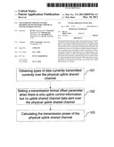
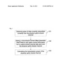
[0052]FIG. 1 is the flow chart for calculating the transmission power of a physical uplink shared channel when there is only uplink control information but no uplink shared channel data sent over a physical uplink shared channel in the embodiments of the present disclosure.
DETAILED DESCRIPTION
[0053]The basic thought of the present disclosure is that, when there is only uplink control information but no uplink shared channel data sent over a physical uplink shared channel, a transmission format offset parameter is set according to the total number of bits contained in a channel quality indication signaling and its corresponding Cyclic Redundancy Check (CRC) as well as an amplitude offset, and then the transmission power of a physical uplink shared channel is set according to the transmission format offset parameter.
[0054]As shown in FIG. 1, a transmission power control method for a physical uplink shared channel in accordance with an embodiment of the present disclosure includes the following steps:
[0055]step 101: Obtaining types of data currently transmitted over the physical uplink shared channel;
[0056]step 102: Setting a transmission format offset parameter when there is only uplink control information but no uplink shared channel data sent over the physical uplink shared channel;
[0057]step 103: Calculating the transmission power of the physical uplink shared channel, and setting the transmission power of the physical uplink shared channel according to the result of the calculation.
[0058]In step 102, the transmission format offset parameter is set according to the total number of bits contained in a channel quality indication signaling and its corresponding cyclic redundancy check as well as an amplitude offset; in step 103, the transmission power of the physical uplink shared channel is set according to the transmission format offset parameter.
EMBODIMENT 1
[0059]The formula for calculating the transmission power of a physical uplink shared channel is as follows:
PPUSCH(i)=min{PMAX,10log10(MPUSCH(i))+PO--.s- ub.PUSCH(j)+αPL+ΔTF(i)+f(i)},
[0060]where PMAX represents an upper limit of transmission power;
[0061]MPUSCH(i) represents bandwidth used for transmitting the PUSCH in subframe i;
[0062]PO--PUSCH(j) represents target reference power (For specific definition, please refer to the definition in section 5.1.1.1 of TS 36.213 (LTE physical layer));
[0063]α represents a path loss correction factor;
[0064]PL represents path loss;
[0065]ΔTF(i) is called as a transmission format offset parameter.
[0066]When KS=1.25, ΔTF(i)=10log10((2MPRKS-1))Δβ); when KS=0, ΔTF(i)=0; KS is a parameter configured by radio resource control at a high layer; MPR=O/NRE, where NRE represents the number of resource elements, NRE=MPUSCHNscRBNsymbPUSCH, where MPUSCH represents the bandwidth used for transmitting the physical uplink shared channel, NsymbPUSCH represents the number of single carrier-frequency division multiple access symbols used for transmitting the PUSCH, NscRB represents the number of resource elements contained in a resource block, O represents the size of information bits, and Δβ represents an amplitude offset.
[0067]When there is only uplink control information but no uplink shared channel data sent over the physical uplink shared channel, O=OCQI and Δβ=βoffsetCQI, where OCQI represents the total number of bits contained in a channel quality indication signaling and its corresponding cyclic redundancy check, βoffsetCQI represents an amplitude offset of channel quality indication information, which is notified by a high layer signaling, and MPUSCH is obtained according to a signaling in an initial PDCCH of a transmission block.
[0068]In other cases (when there is only uplink shared channel data sent over the physical uplink shared channel, or when there are both uplink control information and uplink shared channel data sent over the physical uplink shared channel), O=TBS and Δβ=1, where TBS represents the size of a transmission block, TBS and MPUSCH are obtained according to a signaling in an initial PDCCH of the transmission block.
[0069]βoffsetCQI represents the amplitude offset of channel quality indication information, which is notified by a high layer index IoffsetCQI. The correspondence between the high layer index IoffsetCQI and βoffsetCQI is shown in Table 1. However, in the present disclosure, the correspondence between the high level index IoffsetCQI and βoffsetCQI is not limited to that as shown in Table 1, and may be in other ways.
TABLE-US-00001 TABLE 1 Correspondence between the high layer index IoffsetCQI and βoffsetCQI IoffsetCQI βoffsetCQI 0 0.750 1 1.000 2 1.125 3 1.250 4 1.375 5 1.625 6 1.750 7 2.000 8 2.250 9 2.500 10 2.875 11 3.125 12 3.500 13 4.000 14 5.000 15 6.250 f(i) represents a power control correction function of subframe i.
[0070]Moreover, the uplink control information includes: Acknowledge (ACK), and/or Non-Acknowledge (NACK), and/or Rank Indication (RI), Channel Quality Indication (CQI), and/or Precoding Matrix Indicator (PMI).
EMBODIMENT 2
[0071]The formula for calculating the transmission power of a physical uplink shared channel is shown as follows:
PPUSCH(i)=min{PMAX,10log10(MPUSCH(i))+PO--.s- ub.PUSCH(j)+αPL+ΔTF(i)+f(i)},
[0072]where PMAX represents an upper limit of the transmission power;
[0073]MPUSCH(i) represents bandwidth used for transmitting the PUSCH in subframe i;
[0074]PO--PUSCH(j) represents target reference power (For specific definition, please refer to the definition in section 5.1.1.1 of TS 36.213 (LTE physical layer));
[0075]α represents a path loss correction factor;
[0076]PL represents path loss;
[0077]ΔTF(i) is called as a transmission format offset parameter.
[0078]When KS=1.25, ΔTF(i)=10log10((2MPRKS-1)Δβ); when KS=0, ΔTF=0; KS is a parameter configured by radio resource control at a high layer; MPR=O/NRE, where NRE represents the number of resource elements, NRE=MPUSCHNscRBNsymbPUSCH, where MPUSCH represents the bandwidth used for transmitting the physical uplink shared channel, NsymbPUSCH represents the number of single carrier-frequency division multiple access symbols used for transmitting the PUSCH, NscRB represents the number of resource elements contained in a resource block, O represents the size of information bits, and Δβ represents an amplitude offset.
[0079]When there is only uplink control information but no uplink shared channel data sent over the physical uplink shared channel, O=OCQI and Δβ=βoffsetCQI, where OCQI represents the total number of bits contained in a channel quality indication signaling and its corresponding cyclic redundancy check, βoffsetCQI represents an amplitude offset of channel quality indication information, which is notified by a high layer signaling, and MPUSCH is obtained according to a signaling in an initial PDCCH of a transmission block.
[0080]When there are both uplink control information and uplink shared channel data sent over the physical uplink shared channel, O=TBS and Δβ=1, where TBS represents the size of a transmission block, and TBS and MPUSCH are obtained according to a signaling in an initial PDCCH of the transmission block.
[0081]When there is only uplink shared channel data sent over the physical uplink shared channel, O=TBS and Δβ=1, where TBS represents the size of a transmission block, and TBS and MPUSCH are obtained according to a signaling in a most recent PDCCH related to the transmission block.
[0082]βoffsetCQI represents the amplitude offset of channel quality indication information, which is notified by a high layer index IoffsetCQI. The correspondence between the high layer index IoffsetCQI and βoffsetCQI is shown in Table 1. However, in the present disclosure, the correspondence between the high layer index IoffsetCQI and βoffsetCQI is not limited to that as shown in Table 1, and may be in other ways.
[0083]f(i) represents a power control correction function of subframe i.
[0084]Moreover, the uplink control information includes: Acknowledge (ACK), and/or Non-Acknowledge (NACK), and/or Rank Indication (RI), Channel Quality Indication (CQI), and/or Precoding Matrix Indicator (PMI).
EMBODIMENT 3
[0085]The formula for calculating the transmission power of a physical uplink shared channel is as follows:
PPUSCH(i)=min{PMAX,10log10(MPUSCH(i))+PO--.s- ub.PUSCH(j)+αPL+ΔTF(i)+f(i)},
[0086]where PMAX represents an upper limit of transmission power;
[0087]MPUSCH(i) represents bandwidth used for transmitting the PUSCH in subframe i;
[0088]PO--PUSCH(j) represents target reference power (For specific definition, please refer to the definition in section 5.1.1.1 of TS 36.213 (LTE physical layer));
[0089]α represents a path loss correction factor;
[0090]PL represents path loss;
[0091]ΔTF(i) is called as a transmission format offset parameter.
[0092]When KS=1.25, ΔTF(i)=10log10((2MPRKS-1)Δβ); when KS=0, ΔTF(i)=0; KS is a parameter configured by radio resource control at a high layer; MPR=O/NRE, where NRE represents the number of resource elements, NRE=MPUSCHNscRBNsymbPUSCH, where MPUSCH represents the bandwidth used for transmitting the physical uplink shared channel, NsymbPUSCH represents the number of single carrier-frequency division multiple access symbols used for transmitting the PUSCH, NscRB represents the number of resource elements contained in a resource block, O represents the size of information bits, and Δβ represents an amplitude offset.
[0093]When there is only uplink control information but no uplink shared channel data sent over the physical uplink shared channel, O=OCQI and Δβ=βoffsetCQI, where OCQI represents the total number of bits contained in a channel quality indication signaling and its corresponding cyclic redundancy check, βoffsetCQI represents an amplitude offset of channel quality indication information, which is notified by a high layer signaling, and MPUSCH is obtained according to a signaling in an initial PDCCH of a transmission block.
[0094]In other cases (when there are both uplink control information and uplink shared channel data sent over the physical uplink shard channel, or when there is only uplink shared channel data sent over the physical uplink shared channel),
O = r = 0 C - 1 K r ##EQU00005##
and Δβ=1, where C represents the total number of coding blocks, Kr represents the number of bits contained in a coding block with an index of r, and MPUSCH, C and Kr are obtained according to a signaling in an initial PDCCH of a transmission block.
[0095]βoffsetCQI represents the amplitude offset of channel quality indication information, which is notified by a high layer index IoffsetCQI. The correspondence between the high layer index IoffsetCQI and βoffsetCQI is shown in Table 1. However, in the present disclosure, the correspondence between the high layer index IoffsetCQI and βoffsetCQI is not limited to that as shown in Table 1, and may be in other ways.
[0096]f(i) represents a power control correction function of subframe i.
[0097]Moreover, the uplink control information includes: Acknowledge (ACK), and/or Non-Acknowledge (NACK), and/or Rank Indication (RI), Channel Quality Indication (CQI), and/or Precoding Matrix Indicator (PMI).
EMBODIMENT 4
[0098]The formula for calculating the transmission power of a physical uplink shared channel is as follows:
PPUSCH=min{PMAX,10log10(MPUSCH(i)+PO--.sub.P- USCH(j)+αPL+ΔTF(i)+f(i)},
[0099]where PMAX represents an upper limit of transmission power;
[0100]MPUSCH(i) represents bandwidth used for transmitting the PUSCH in subframe i;
[0101]PO--.sub.PUSH(j) represents target reference power (For specific definition, please refer to the definition in section 5.1.1.1 of TS 36.213 (LTE physical layer));
[0102]α represents a path loss correction factor;
[0103]PL represents path loss;
[0104]ΔTF(i) is called as a transmission format offset parameter.
[0105]When KS=1.25, ΔTF(i)=10log10((2MPRKS-1)Δβ); when KS=0, ΔTF(i)=0; KS is a parameter configured by radio resource control at a high layer; MPR=O/NRE, where NRE represents the number of resource elements, NRE=MPUSCHNscRBNsymbPUSCH, where MPUSCH represents the bandwidth used for transmitting the physical uplink shared channel, NsymbPUSCH represents the number of single carrier-frequency division multiple access symbols used for transmitting the PUSCH, NscRB represents the number of resource elements contained in a resource block, O represents the size of information bits, and Δβ represents an amplitude offset.
[0106]When there is only uplink control information but no uplink shared channel data sent over the physical uplink shared channel, O=OCQI and Δβ=βoffsetCQI, where OCQI represents the total number of bits contained in a channel quality indication signaling and its corresponding cyclic redundancy check, βoffsetCQI represents an amplitude offset of channel quality indication information, which is notified by a high layer signaling, and MPUSCH is obtained according to a signaling in an initial PDCCH of a transmission block.
[0107]When there are both uplink control information and uplink shared channel data sent over the physical uplink shared channel,
O = r = 0 C - 1 K r ##EQU00006##
and Δβ=1, where C represents the total number of coding blocks, Kr represents the number of bits contained in a coding block with an index of r, and MPUSCH, C and Kr are obtained according to a signaling in an initial PDCCH of a transmission block.
[0108]When there is only uplink shared channel data sent over the physical uplink shared channel,
O = r = 0 C - 1 K r ##EQU00007##
and Δβ=1, where C represents the total number of coding blocks, Kr represents the number of bits contained in a coding block with an index of r, and MPUSCH, C and Kr are obtained according to a signaling in a most recent PDCCH related to the transmission block.
[0109]βoffsetCQI represents the amplitude offset of channel quality indication information, which is notified by a high layer index IoffsetCQI. The correspondence between the high layer index IoffsetCQI and βoffsetCQI is shown in Table 1. However, in the present disclosure, the correspondence between the high layer index IoffsetCQI and βoffsetCQI is not limited to that as shown in Table 1, and may be in other ways.
[0110]f(i) represents a power control correction function of subframe i.
[0111]Moreover, the uplink control information includes: Acknowledge (ACK), and/or Non-Acknowledge (NACK), and/or Rank Indication (RI), Channel Quality Indication (CQI), and/or Precoding Matrix Indicator (PMI).
EMBODIMENT 5
[0112]The formula for calculating the transmission power of a physical uplink shared channel is as follows:
PPUSCH=min{PMAX, 10log10(MPUSCH(i)+PO--PUSCH(j)+αPL+Δ- TF(i)+f(i)},
[0113]where PMAX represents an upper limit of transmission power;
[0114]MPUSCH(i) represents bandwidth used for transmitting the PUSCH in subframe i;
[0115]PO--PUSCH(j) represents target reference power (For specific definition, please refer to the definition in section 5.1.1.1 of TS 36.213 (LTE physical layer));
[0116]α represents a path loss correction factor;
[0117]PL represents path loss;
[0118]ΔTF(i) is called as a transmission format offset parameter.
[0119]When KS=1.25, ΔTF(i)=10log10(2MPRKS-1)+Δβ; when KS=0, ΔTF(i)=0; KS is a parameter configured by radio resource control at a high layer; MPR=O/NRE, where NRF represents the number of resource elements, NRE=MPUSCHNscRBNsymbPUSCH, where MPUSCH represents the bandwidth used for transmitting the physical uplink shared channel, NsymbPUSCH represents the number of single carrier-frequency division multiple access symbols used for transmitting the PUSCH, NscRB represents the number of resource elements contained in a resource block, O represents the size of information bits, and Δβ represents an amplitude offset.
[0120]When there is only uplink control information but no uplink shared channel data sent over the physical uplink shared channel, O=OCQI and Δβ=10log10 βoffsetCQI, where OCQI represents the total number of bits contained in a channel quality indication signaling and its corresponding cyclic redundancy check, βoffsetCQI represents an amplitude offset of channel quality indication information, which is notified by a high layer signaling, and MPUSCH is obtained according to a signaling in an initial PDCCH of a transmission block.
[0121]In other cases (when there is only uplink shared channel data sent over the physical uplink shared channel, or when there are both uplink control information and uplink shared channel data sent over the physical uplink shared channel), O=TBS and Δβ=0, where TBS represents the size of a transmission block, and TBS and MPUSCH are obtained according to a signaling in an initial PDCCH of the transmission block.
[0122]βoffsetCQI represents the amplitude offset of channel quality indication information, which is notified by a high layer index IoffsetCQI. The correspondence between the high layer index IoffsetCQI and βoffsetCQI is shown in Table 1. However, in the present disclosure, the correspondence between the high layer index IoffsetCQI and IoffsetCQI is not limited to that as shown in Table 1, and may be in other ways.
[0123]f(i) represents a power control correction function of subframe i.
[0124]Moreover, the uplink control information includes: Acknowledge (ACK), and/or Non-Acknowledge (NACK), and/or Rank Indication (RI), Channel Quality Indication (CQI), and/or Precoding Matrix Indicator (PMI).
EMBODIMENT 6
[0125]The formula for calculating the transmission power of a physical uplink shared channel is as follows:
PPUSCH(i)=min{PMAX,10log10(MPUSCH(i)+PO--.su- b.PUSCH(j)+αPL+ΔTF(i)+f(i)},
[0126]where PMAX represents an upper limit of transmission power;
[0127]MPUSCH(i) represents bandwidth used for transmitting the PUSCH in subframe i;
[0128]PO--PUSCH(j) represents target reference power (For specific definition, please refer to the definition in section 5.1.1.1 of TS 36.213 (LTE physical layer));
[0129]α represents a path loss correction factor;
[0130]PL represents path loss;
[0131]ΔTF(i) is called as a transmission format offset parameter.
[0132]When KS=1.25, ΔTF(i)=10log10(2MPRKS-1)+Δβ; when KS=0, ΔTF(i)=0; KS is a parameter configured by radio resource control at a high layer; MPR=O/NRE, where NRE represents the number of resource elements, NRE=MPUSCHNscRBNsymbPUSCH, where MPUSCH represents the bandwidth used for transmitting the physical uplink shared channel, NsymbPUSCH represents the number of single carrier-frequency division multiple access symbols used for transmitting the PUSCH, NscRB represents the number of resource elements contained in a resource block, O represents the size of information bits, and Δβ represents an amplitude offset.
[0133]When there is only uplink control information but no uplink shared channel data sent over the physical uplink shared channel, O=OCQI and Δβ=10log10 βoffsetCQI, where OCQI represents the total number of bits contained in a channel quality indication signaling and its corresponding cyclic redundancy check, βoffsetCQI represents an amplitude offset of channel quality indication information, which is notified by a high layer signaling, and MPUSCH is obtained according to a signaling in an initial PDCCH of a transmission block.
[0134]When there are both uplink control information and uplink shared channel data sent over the physical uplink shared channel, O=TBS and Δβ=0, where TBS represents the size of a transmission block, and TBS and MPUSCH are obtained according to a signaling in an initial PDCCH of the transmission block.
[0135]When there is only uplink shared channel data sent over the physical uplink shared channel, O=TBS and Δβ=0, where TBS represents the size of a transmission block, and TBS and MPUSCH are obtained according to a signaling in a most recent PDCCH related to the transmission block;
[0136]βoffsetCQI represents the amplitude offset of channel quality indication information, which is notified by a high layer index IoffsetCQI. The correspondence between the high layer index IoffsetCQI and βoffsetCQI is shown in Table 1. However, in the present disclosure, the correspondence between the high layer index IoffsetCQI and βoffsetCQI is not limited to that as shown in Table 1, and may be in other ways.
[0137]f(i) represents a power control correction function of subframe i.
[0138]Moreover, the uplink control information includes: Acknowledge (ACK), and/or Non-Acknowledge (NACK), and/or Rank Indication (RI), Channel Quality Indication (CQI), and/or Precoding Matrix Indicator (PMI).
EMBODIMENT 7
[0139]The formula for calculating the transmission power of a physical uplink shared channel is as follows:
PPUSCH(i)=min{PMAX,10log10(MPUSCH(i)+PO--.su- b.PUSCH(j)+αPL+ΔTF(i)+f(i)},
[0140]where PMAX represents an upper limit of transmission power;
[0141]MPUSCH(i) represents bandwidth used for transmitting the PUSCH in subframe i;
[0142]PO--PUSCH(j) represents target reference power (For specific definition, please refer to the definition in section 5.1.1.1 of TS 36.213 (LTE physical layer));
[0143]α represents a path loss correction factor;
[0144]PL represents path loss;
[0145]ΔTF(i) is called as a transmission format offset parameter.
[0146]When KS=1.25, ΔTF(i)=10log10(2MPRKS-1)+Δβ; when KS=0, ΔTF(i)=0; KS is a parameter configured by radio resource control at a high layer; MPR=O/NRE, where NRE represents the number of resource elements, NRE=MPUSCHNscRBNsymbPUSCH, where MPUSCH represents the bandwidth used for transmitting the physical uplink shared channel, NsymbPUSCH represents the number of single carrier-frequency division multiple access symbols used for transmitting the PUSCH, NRscRB represents the number of resource elements contained in a resource block, O represents the size of information bits, and Δβ represents an amplitude offset.
[0147]When there is only uplink control information but no uplink shared channel data sent over the physical uplink shared channel, O=OCQI and Δβ=10log10 βoffsetCQI, where OCQI represents the total number of bits contained in a channel quality indication signaling and its corresponding cyclic redundancy check, βoffsetCQI represents an amplitude offset of channel quality indication information, which is notified by a high layer signaling, and MPUSCH is obtained according to a signaling in an initial PDCCH of a transmission block.
[0148]In other cases (when there are both uplink control information and uplink shared channel data sent over the physical uplink shared channel, or when there is only uplink shared channel data sent over the physical uplink shared channel),
O = r = 0 C - 1 K r ##EQU00008##
and Δβ=0, where C represents the total number of coding blocks, Kr represents the number of bits contained in a coding block with an index of r, and MPUSCH, C and Kr are obtained according to a signaling in an initial PDCCH of a transmission block.
[0149]βoffsetCQI represents the amplitude offset of channel quality indication information, which is notified by a high layer index IoffsetCQI. The correspondence between the high layer index IoffsetCQI and βoffsetCQI is shown in Table 1. However, in the present disclosure, the correspondence between the high layer index IoffsetCQI and βoffsetCQI is not limited to that as shown in Table 1, and may be in other ways.
[0150]f(i) represents a power control correction function of subframe i.
[0151]Moreover, the uplink control information includes: Acknowledge (ACK), and/or Non-Acknowledge (NACK), and/or Rank Indication (RI), Channel Quality Indication (CQI), and/or Precoding Matrix Indicator (PMI).
EMBODIMENT 8
[0152]The formula for calculating the transmission power of a physical uplink shared channel is as follows:
PPUSCH(i)=min{PMAX,10log10(MPUSCH(i))+PO--.s- ub.PUSCH(j)+αPL+ΔTF(i)+f(i)},
[0153]where PMAX represents an upper limit of transmission power;
[0154]MPUSCH(i) represents bandwidth used for transmitting the PUSCH in the subframe i;
[0155]PO--PUSCH(j) represents target reference power (For specific definition, please refer to the definition in section 5.1.1.1 of TS 36.213 (LTE physical layer));
[0156]α represents a path loss correction factor;
[0157]PL represents path loss;
[0158]ΔTF(i) is called as a transmission format offset parameter.
[0159]When KS=1.25, ΔTF(i)=10log10(2MPRKS-1)+Δβ; when KS=0, ΔTF(i)=0; KS is a parameter configured by radio resource control at a high layer; MPR=O/NRE, where NRE represents the number of resource elements, NRE=MPUSCHNscRBNsymbPUSCH, where MPUSCH represents the bandwidth used for transmitting the physical uplink shared channel, NsymbPUSCH represents the number of single carrier-frequency division multiple access symbols used for transmitting the PUSCH; NscRB represents the number of resource elements contained in a resource block, O represents the size of information bits, and Δβ represents an amplitude offset.
[0160]When there is only uplink control information but no uplink shared channel data sent over the physical uplink shared channel, O=OCQI and Δβ=10log10 βoffsetCQI, where OCQI represents the total number of bits contained in a channel quality indication signaling and its corresponding cyclic redundancy check, βoffsetCQI represents an amplitude offset of channel quality indication information, which is notified by a high layer signaling, and MPUSCH is obtained according to a signaling in an initial PDCCH of a transmission block.
[0161]Where there are both uplink control information and uplink shared channel data sent over the physical uplink shared channel,
O = r = 0 C - 1 K r ##EQU00009##
and Δβ=0, where C represents the total number of coding blocks, Kr represents the number of bits contained in a coding block with an index of r, and MPUSCH, C and Kr are obtained according to a signaling in an initial PDCCH of a transmission block.
[0162]When there is only uplink shared channel data sent over the physical uplink shared channel,
O = r = 0 C - 1 K r ##EQU00010##
and Δβ=0, where C represents the total number of coding blocks, Kr represents the number of bits contained in a coding block with an index of r, and MPUSCH, C and Kr are obtained according to a signaling in a most recent PDCCH related to the transmission block.
[0163]βoffsetCQI represents the amplitude offset of channel quality indication information, which is notified by a high layer index IoffsetCQI. The correspondence between the high layer index IoffsetCQI and βoffsetCQI is shown in Table 1. However, in the present disclosure, the correspondence between the high layer index IoffsetCQI and βoffsetCQI is not limited to that as shown in Table 1, and may be in other ways.
[0164]f(i) represents a power control correction function of subframe i.
[0165]Moreover, the uplink control information includes: Acknowledge (ACK), and/or Non-Acknowledge (NACK), and/or Rank Indication (RI), Channel Quality Indication (CQI), and/or Precoding Matrix Indicator (PMI).
[0166]The present disclosure also provides a transmission power control system for a physical uplink shared channel. The system includes: a power setting module, used for setting the transmission power of the physical uplink shared channel according to the total number of bits contained in a channel quality indication signaling and its corresponding cyclic redundancy check as well as an amplitude offset, when there is only uplink control information but no uplink shared channel data sent over the physical uplink shared channel.
[0167]Wherein the power setting module is used for setting the transmission power of the physical uplink shared channel according to the following formula:
PPUSCH(i)=min{PMAX,10log10(MPUSCH(i)+PO--.su- b.PUSCH(j)+αPL+ΔTF(i)+f(i)},
[0168]where PMAX represents an upper limit of transmission power;
[0169]MPUSCH(i) represents bandwidth used for transmitting the physical uplink shared channel in subframe i;
[0170]PO--PUSCH(j) represents target reference power;
[0171]α represents a path loss correction factor;
[0172]PL represents path loss;
[0173]f(i) represents a power control correction function of subframe i; ΔTF(i) is a transmission format offset parameter;
[0174]when KS=1.25, ΔTF(i)=10log10((2MPRKS-1)Δβ), or ΔTF(i)=10log10(2MPRKS-1)+Δβ; when KS=0, ΔTF(i)=0; KS is a parameter configured by radio resource control at a high layer; MPR=O/NRE, where NRE represents the number of resource elements, NRE=MPUSCHNscRBNsymbPUSCH, where MPUSCH represents the bandwidth used for transmitting the physical uplink shared channel, NsymbPUSCH represents the number of single carrier-frequency division multiple access symbols used for transmitting the PUSCH, NscRB represents the number of resource elements contained in a resource block, O represents the size of information bits, and Δβ represents the amplitude offset;
[0175]wherein when there is only uplink control information but no uplink shared channel data sent over the physical uplink shared channel, O=OCQI, and when ΔTF(i)=10log10((2MPRKS-1)Δβ), Δβ=βoffsetCQI, or when ΔTF(i)=10log10(2MPRKS-1)+Δβ, Δβ=10log10 βoffsetCQI, where OCQI represents the total number of bits contained in the channel quality indication signaling and its corresponding cyclic redundancy check, βoffsetCQI represents an amplitude offset of channel quality indication information, and MPUSCH is obtained according to a signaling in an initial PDCCH of a transmission block. The power setting module obtains the βoffsetCQI from a high layer signaling.
[0176]The power setting module is also used for determining values of O and Δβ in the following way when there is only uplink shared channel data sent over the physical uplink shared channel, or when there are both uplink control information and uplink shared channel data sent over the physical uplink shared channel: O=TBS, when ΔTF(i)=10log10((2MPRKS-1)Δβ), Δβ=1, or when ΔTF(i)=10log10(2MPRKS-1)+Δβ, Δβ=0, where TBS represents the size of a transmission block, and TBS and MPUSCH are obtained according to the signaling in the initial PDCCH of the transmission block.
[0177]The power setting module is also used for determining values of O and Δβ in the following way when there is only uplink shared channel data sent over the physical uplink shared channel: O=TBS, when ΔTF(i)=10log10((2MPRKS-1)Δβ), Δβ=1, or when ΔTF(i)=10log10(2MPRKS-1)+Δβ, Δβ=0, where TBS represents the size of a transmission block, and TBS and MPUSCH are obtained according to a signaling in a most recent PDCCH related to the transmission block.
[0178]The power setting module is also used for determining values of O and Δβ in the following way when there is only uplink shared channel data sent over the physical uplink shared channel, or when there are both uplink control information and uplink shared channel data sent over the physical uplink shared channel:
O = r = 0 C - 1 K r , ##EQU00011##
when ΔTF(i)=10log10((2MPRKS-1)Δβ), Δβ=1, or when ΔTF(i)=10log10(2MPRKS-1)+Δβ, Δβ=0, where C represents the total number of coding blocks, Kr represents the number of bits contained in a coding block with an index of r, and the MPUSCH, C and Kr are obtained according to the signaling in the initial PDCCH of the transmission block.
[0179]The power setting module is also used for determining values of O and Δβ in the following way when there is only uplink shared channel data sent over the physical uplink shared channel:
O = r = 0 C - 1 K r , ##EQU00012##
when ΔTF(i)=10log10((2MPRKS-1)Δβ), Δβ=1, or when ΔTF(i)=10log10(2MPRKS-1)+Δβ, Δβ=0, where C represents the total number of coding blocks, Kr represents the number of bits contained in a coding block with an index of r, and the MPUSCH, C and Kr are obtained according to a signaling in a most recent PDCCH related to the transmission block.
[0180]The foregoing descriptions are only preferred embodiments of the present disclosure, and are not intended to limit the present disclosure. For those skilled in the art, the present disclosure may have various changes and modifications. All modifications, identical replacements and improvements made without departing from the spirit and principle of the present disclosure shall be within the protection scope of the present disclosure.
INDUSTRIAL APPLICABILITY
[0181]The present disclosure provides a transmission power control method and a system for a physical uplink shared channel, which are used for setting the transmission power of the physical uplink shared channel according to the total number of bits contained in a channel indication signaling and its corresponding cyclic redundancy check as well as an amplitude offset when there is only uplink control information but no uplink shared channel data sent over the physical uplink shared channel, thus to ensure the overall performance of a system.
User Contributions:
comments("1"); ?> comment_form("1"); ?>Inventors list |
Agents list |
Assignees list |
List by place |
Classification tree browser |
Top 100 Inventors |
Top 100 Agents |
Top 100 Assignees |
Usenet FAQ Index |
Documents |
Other FAQs |
User Contributions:
Comment about this patent or add new information about this topic:
Images included with this patent application:
 |  |
| Similar patent applications: | |
| Date | Title |
|---|---|
| 2009-12-31 | Transmission power control method of uplink packet data transmission |
| 2010-01-14 | Signal transmission parameter control using channel sounding |
| 2009-07-16 | Transmission of data bursts on a constant data rate channel |
| 2008-10-30 | Power control of point to multipoint physical channels |
| 2009-02-26 | Transmission power level regulation for high priority wireless calls |
| New patent applications from these inventors: | |
| Date | Title |
|---|---|
| 2022-09-15 | Paging information transmission method, apparatus and system |
| 2022-09-08 | Scheduling indication method and apparatus, and storage medium |
| 2022-09-08 | Uplink information feedback resource determination method and device |
| 2022-09-08 | Data sending method and apparatus, data receiving method and apparatus, first node, and second node |
| Top Inventors for class "Telecommunications" | |
| Rank | Inventor's name |
|---|---|
| 1 | Ahmadreza (reza) Rofougaran |
| 2 | Jeyhan Karaoguz |
| 3 | Ahmadreza Rofougaran |
| 4 | Mehmet Yavuz |
| 5 | Maryam Rofougaran |