Patent application title: LOCKING MECHANISM
Inventors:
Foley Kevin (Germantown, TN, US)
Newt Metcalf (Memphis, TN, US)
Greg Marik (Collierville, TN, US)
Assignees:
WARSAW ORTHOPEDIC, INC.
IPC8 Class: AA61B1780FI
USPC Class:
606290
Class name: Including anchoring means screw retention means (e.g., anti-backup) locking ring or washer
Publication date: 2011-03-03
Patent application number: 20110054543
Inventors list |
Agents list |
Assignees list |
List by place |
Classification tree browser |
Top 100 Inventors |
Top 100 Agents |
Top 100 Assignees |
Usenet FAQ Index |
Documents |
Other FAQs |
Patent application title: LOCKING MECHANISM
Inventors:
Foley Kevin
Greg Marik
Newt Metcalf
Agents:
Assignees:
Origin: ,
IPC8 Class: AA61B1780FI
USPC Class:
Publication date: 03/03/2011
Patent application number: 20110054543
Abstract:
A stratum to be affixed to bone is disclosed. The stratum has a first
surface, a second surface, and at least one hole extending between the
first surface and the second surface, wherein the second surface is
configured to engage at least a portion of the bone, and wherein the
stratum is further configured to deflect, allowing a fastener to pass at
least partially through the hole.Claims:
1. A stratum to be affixed to bone, the stratum comprising:a first
surface, a second surface, and at least one hole extending between the
first surface and the second surface, wherein the second surface is
configured to engage at least a portion of the bone, and wherein the
stratum is further configured to deflect, allowing a fastener to pass at
least partially through the hole.
2. A system for affixing the stratum of claim 1 to the bone, wherein the fastener comprises:a length and a width, the length being greater than the width, and a central longitudinal axis;a head portion;an intermediate portion; anda distal portion, wherein the distal portion has a proximal end that is proximate the intermediate portion, and the proximal end has a width substantially perpendicular to the central longitudinal axis so that the proximal end causes the stratum to deflect as the proximal end of the fastener moves across the at least one hole in the stratum in the direction towards the second surface of the stratum.
3. The system of claim 2, wherein the distal portion of the fastener has a lip that allows passage of the proximal end through the at least one hole in the stratum, and prevents inadvertent backing out of the fastener.
4. The stratum of claim 1, wherein the fastener is configured to pass at least partially through the at least one hole and engage at least a portion of the bone.
5. The stratum of claim 4, wherein the fastener is a screw that is substantially circular in cross section, and the width is a diameter.
6. The stratum of claim 1, wherein the bone is spine, and wherein the stratum is a spinal plate.
7. The stratum of claim 1, wherein the stratum comprises polyetheretherketone.
8. The stratum of claim 1, wherein the stratum consists essentially of polyetheretherketone.
9. The system of claim 3, wherein the width of the proximate end of the distal portion is a first width and the intermediate portion has a second width, wherein the second width is smaller than the first width.
10. A system for affixing a stratum to bone, the system comprising:a stratum having a first surface, a second surface, and at least one hole extending between the first surface and the second surface, wherein the second surface is configured to engage at least a portion of the bone;a fastener configured to pass at least partially through the at least one hole and engage at least a portion of the bone, wherein the fastener has a length and a width, the length being greater than the width, and a central longitudinal axis, the fastener further comprising:a head portion;an intermediate portion; anda distal portion, wherein the distal portion has a proximal end that is proximate the intermediate portion, and the proximal end has a width substantially perpendicular to the central longitudinal axis, wherein the proximal end causes the stratum to deflect as the proximal end of the fastener moves across the at least one hole in the stratum in the direction towards the second surface of the stratum.
11. The system of claim 10, wherein the distal portion of the fastener has a lip that allows passage of the proximal end through the at least one hole in the stratum, and prevents inadvertent backing out of the fastener.
12. The system of claim 10, wherein the fastener is a screw.
13. The system of claim 12, wherein the screw is substantially circular in cross section, and the width is a diameter.
14. The system of claim 10, wherein the bone is spine, and wherein the stratum is a spinal plate.
15. The system of claim 10, wherein the stratum comprises polyetheretherketone.
16. The system of claim 10, wherein the stratum consists essentially of polyetheretherketone.
17. The system of claim 12, wherein the width of the proximate end of the distal portion is a first width and the intermediate portion has a second width, wherein the second width is smaller than the first width.
18. A system for affixing a stratum to bone, the system comprising:a stratum having a first surface, a second surface, and at least one hole extending between the first surface and the second surface, wherein the second surface is configured to engage at least a portion of the bone;a fastener configured to pass at least partially through the at least one hole and engage at least a portion of the bone, wherein the fastener has a length and a width, the length being greater than the width, and a central longitudinal axis, the fastener further comprising:a head portion;an intermediate portion; anda distal portion, wherein the distal portion has a proximal end that is proximate the intermediate portion, and the proximal end has a width substantially perpendicular to the central longitudinal axis, wherein the proximal end causes the stratum to deflect as the proximal end of the fastener moves across the at least one hole in the stratum in the direction towards the second surface of the stratum, the distal portion having a lip that allows passage of the proximal end through the at least one hole in the stratum, and prevents the fastener from inadvertent backing out of the fastener, wherein the width of the proximate end of the distal portion is a first width and the intermediate portion has a second width, wherein the second width is smaller than the first width.
19. The system of claim 18, wherein the fastener is a screw that is substantially circular in cross section, and the width is a diameter.
20. The system of claim 19, wherein the bone is spine, the stratum is a spinal plate, and the stratum consists essentially of polyetheretherketone.
Description:
[0001]The present disclosure is related to commonly owned and copending
U.S. application Ser. Nos. ______ (having Attorney Docket No. P35833.00)
and ______ (having Attorney Docket No. P35835.00), each of which has a
filing date that is the same as the present disclosure, and both of which
are hereby incorporated herein by reference in their entireties.
FIELD OF INVENTION
[0002]The present invention is directed to systems for affixing a stratum to bone.
BACKGROUND
[0003]The present disclosure relates to locking mechanisms, and more particularly, systems for affixing a stratum to bone.
SUMMARY OF THE INVENTION
[0004]A stratum to be affixed to bone is disclosed. The stratum has a first surface, a second surface, and at least one hole extending between the first surface and the second surface, wherein the second surface is configured to engage at least a portion of the bone, and wherein the stratum is further configured to deflect, allowing a fastener to pass at least partially through the hole.
[0005]Additional aspects and features of the present disclosure will be apparent from the detailed description and claims as set forth below.
BRIEF DESCRIPTION OF THE DRAWINGS
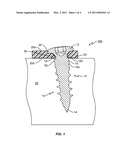
[0006]FIG. 1 is a cross-sectional view of a system for affixing a stratum to bone;
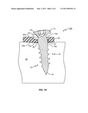
[0007]FIG. 1A is a cross-sectional view of the system of FIG. 1, depicting deflection of the stratum;
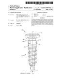
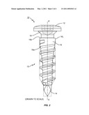
[0008]FIG. 2 is a side view of the fastener of the system of FIG. 1; and
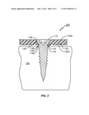
[0009]FIG. 3 is a cross-sectional view of another system for affixing a stratum to bone.
DETAILED DESCRIPTION
[0010]For the purposes of promoting an understanding of the principles of the invention, reference will now be made to the embodiments, or examples, illustrated in the drawings and specific language will be used to describe the same. It will nevertheless be understood that no limitation of the scope of the invention is thereby intended. Any alterations and further modifications in the described embodiments, and any further applications of the principles of the invention as described herein are contemplated as would normally occur to one skilled in the art to which the invention relates.
[0011]FIG. 1 shows a cross-sectional view of a system 100 for affixing a stratum 20 to bone 50. The system 100 has a stratum 20 having a first surface 20a, a second surface 20b, and at least one hole 30 extending between the first surface 20a and the second surface 20b, wherein the second surface 20b is configured to engage at least a portion of the bone 50. The system 100 further has a fastener 10 configured to pass at least partially through the at least one hole 30 and engage at least a portion of the bone 50, wherein the stratum 20 is further configured to deflect, allowing the fastener 10 to pass at least partially through the hole 30. In the context where the stratum 20 may be a spinal plate, for example, the stratum may be used to fuse adjacent vertebrae together in a relatively fixed relationship.
[0012]In the system 100 of FIG. 1, the fastener 10 has a length and a width, the length being greater than the width, and a central longitudinal axis. A side view of the fastener 10 of FIG. 1 is shown in FIG. 2, which is drawn to scale. The fastener 10 further has a head portion 12, an intermediate portion 18, and a distal portion 15. The distal portion 15 has a proximal end 16 that is proximate the intermediate portion 18, and a distal end 14 located at the tip of the fastener 10.
[0013]In the context of spinal plates, the fastener 10 may be, for example, a screw. In fact, a screw is shown as the fastener 10 in FIGS. 1 and 2. In an embodiment where the fastener 10 is a screw, the head portion 12 is a head of the screw, the distal portion 15 contains threads of the screw, and the intermediate portion 18 has no threads. The cross section of the fastener 10 may be substantially circular, as is common with screws. As shown in FIGS. 1 and 2, the head portion 12 has a width (or diameter in the case of a fastener having a circular cross section) that is the largest of the fastener 10, while the intermediate portion 18 has the smallest width (or diameter). The distal portion 15 of the fastener 10 has a proximal end 16 having a first width (or diameter) and a distal end 14 having a second width (or diameter), wherein the first width is greater than the second width. As used herein, the width of each respective section is substantially perpendicular to the central longitudinal axis X-X' of the fastener 10.
[0014]In the embodiment of FIG. 1, the system 100 shows a stratum 20 that is substantially non-rigid, such as, for example, polyetheretherketone ("PEEK"). Such a stratum may be composed solely of PEEK, or contain enough PEEK so as to be non-rigid. Other suitable non-rigid materials may include, but are not limited to polyetherketoneketone ("PEKK"), ultra high molecular weight polyethylene ("UHMWPE"), polyethylene, shape memory metals and other polymers. The term "substantially" as used herein may be applied to modify any quantitative representation which could permissibly vary without resulting in a change in the basic function to which it is related. For example, a stratum 20 may be considered substantially non-rigid if can deflect (at the location of the hole 130) upon the insertion of a fastener 10 through hole 30, but rebound to the position or approximate position prior to insertion of the fastener 10. Specifically, system 100 is designed so that the proximal end 16 of the distal portion 15 of the fastener 10 causes the stratum 20 to deflect as the proximal end 16 of the fastener 10 moves across the at least one hole 30 in the stratum 20 in the direction towards the second surface 20b of the stratum 20. FIG. 1A shows system 100 as the proximal end 16 of the fastener 10 moves across the at least one hole 30 in the stratum 20 in the direction towards the second surface 20b of the stratum 20, thereby deflecting the stratum 20.
[0015]FIG. 1A illustrates a deflection mechanism that is a type of deflection due to, for example, the characteristics of the material of the stratum 20. In addition to the deflection mechanism illustrated in FIG. 1A, the stratum 20 may deflect in a radial direction so as to enlarge the hole 30. That is, the stratum 20 adjacent to the hole 30 or portions of the stratum 20 adjacent the hole 30 may move in a direction away from the fastener 10, yet remain in the same plane of the stratum 20. In such a mechanism, the stratum 20 deflects in a direction away from and substantially perpendicular to the fastener 10. Such a mechanism is a type of deflection due, for example, the geometry of the stratum 20.
[0016]Further, the distal portion 15 of the fastener 10 has a lip 16L that allows passage of the proximal end 16 through the at least one hole 30 in the stratum 20, and prevents inadvertent backing out of the fastener 10, i.e., moving back out of the at least one hole 30 in a direction away from the bone 50. As shown in FIGS. 1, 1A and 2, the lip 16L is situated at the proximal-most location of the distal portion 15 of the fastener 10, and also has the largest width (or diameter) over the distal portion of the fastener 10. Also, when the fastener 10 is inserted through the hole 30 on the stratum 20, the stratum 20 starts to deflect when the surface 16a of the proximal end 16 of the distal portion 15 contacts the stratum 20, whereas the stratum 20 prevents inadvertent backing out of the fastener 10 by means of the contact between the second surface 20b of the stratum 20 and surface 16b of the proximal end 16 of the distal portion 15. In the embodiments of FIGS. 1, 1A and 2, the fastener 10 is made of a material that allows this function to be accomplished. For example, the fastener 10 may be made of a material (metal or non-metal) that is able to cause the stratum 20 to deflect and rebound, as described above. Some suitable materials include, but are not limited to, Titanium Alloys, commercially available Titanium, stainless steel, PEEK, cobalt chrome ("CoCr"), and shape memory metals. Further, as shown in FIG. 1, the stratum 20 has a recess 24 surrounding the hole 30 that helps accommodate at least a portion of the head portion 12 of the fastener 10.
[0017]FIG. 3 shows a cross-sectional view of a system 200 for affixing a stratum 120 to bone 150. The system 200 has a stratum 120 having a first surface 120a, a second surface 120b, and at least one hole 130 extending between the first surface 120a and the second surface 120b, wherein the second surface 120b is configured to engage at least a portion of the bone 150. The system 200 further has a fastener 110 configured to pass at least partially through the at least one hole 130 and engage at least a portion of the bone 150, wherein the stratum 120 is further configured to deflect, allowing the fastener 110 to pass at least partially through the hole 130.
[0018]In system 200 of FIG. 3, the fastener 110 has a length and a width, the length being greater than the width, and a central longitudinal axis. The fastener 110 further has a head portion 112, an intermediate portion 118, and a distal portion 115. The distal portion 115 has a proximal end 116 that is proximate the intermediate portion 118, and a distal end 114 located at the tip of the fastener 110.
[0019]In the context of spinal plates, the fastener 110 may be, for example, a screw. In fact, a screw is shown as the fastener 110 in FIG. 3. In an embodiment where the fastener 110 is a screw, the head portion 112 is a head of the screw, the distal portion 115 contains threads of the screw, and the intermediate portion 118 has no threads. The cross section of the fastener 110 may be substantially circular, as is common with screws. As shown in FIG. 3, the head portion 112 has a width (or diameter) that is the largest of the fastener 10, while the intermediate portion 118 has the smallest width (or diameter). The distal portion 115 of the fastener 110 has a proximal end 116 having a first width (or diameter) and a distal end 114 having a second width (or diameter), wherein the first width is greater than the second width. As in the embodiments of FIGS. 1, 1A and 2, as used herein, the width of each respective section is substantially perpendicular to the central longitudinal axis of the fastener 110.
[0020]In the embodiment of FIG. 3, the system 100 shows a stratum 120 that is substantially non-rigid, such as, for example, polyetheretherketone ("PEEK"). Such a stratum may be composed solely of PEEK, or contain enough PEEK so as to be non-rigid. Other suitable materials for the stratum 120 of FIG. 3 are similar to those that are suitable for the stratum 20 of FIGS. 1 and 1A. A stratum 120 may be considered substantially non-rigid if can deflect (at the location of the hole 30) upon the insertion of a fastener 110 through hole 130, but rebound to the position or approximate position prior to insertion of the fastener 110. Specifically, system 200 is designed so that the proximal end 116 of the distal portion 115 of the fastener 110 causes the stratum 120 to deflect as the proximal end 116 of the fastener 110 moves across the at least one hole 130 in the stratum 120 in the direction towards the second surface 120b of the stratum 120.
[0021]Further, the distal portion 115 of the fastener 110 has a lip 116L that allows passage of the proximal end 116 through the at least one hole 130 in the stratum 120, and prevents inadvertent backing out of the fastener 110, i.e., moving back out of the at least one hole 130 in a direction away from the bone 150. As shown in FIG. 3, the lip 116L is situated at the proximal-most location of the distal portion 115 of the fastener 110, and also has the largest width (or diameter) over the distal portion of the fastener 110. Also, when the fastener 110 is inserted through the hole 130 on the stratum 120, the stratum 120 starts to deflect when the surface 116a of the proximal end 116 of the distal portion 115 contacts the stratum 120, whereas the stratum 120 prevents inadvertent backing out of the fastener 110 by means of the contact between the second surface 120b of the stratum 120 and surface 116b of the proximal end 116 of the distal portion 115. In the embodiment of FIG. 3, as with those illustrated in the previous Figures, the fastener 110 is made of a material that allows this function to be accomplished. For example, the fastener 110 may be made of a material (metal or non-metal) that is able to cause the stratum 120 to deflect and rebound, as described above. As with system 100 of the previous figures, with the system 200 of FIG. 3, the stratum 120 and the lip 116L of the fastener 110 are configured and work in conjunction to allow deflection of the stratum 120 in the direction toward the bone 150, while at the same time, work to not allow deflection in the opposite direction, i.e., to prevent inadvertent backing out of the fastener. Further, as shown in FIG. 3, the stratum 120 has a recess 124 surrounding the hole 130 that helps accommodate at least a portion of the head portion 112 of the fastener 110.
[0022]All adjustments and alternatives described above are intended to be included within the scope of the invention, as defined exclusively in the following claims. Those skilled in the art also should realize that such modifications and equivalent constructions or methods do not depart from the spirit and scope of the present disclosure, and that they may make various changes, substitutions, and alterations herein without departing from the spirit and scope of the present disclosure. Furthermore, as used herein, the terms components and modules may be interchanged. It is understood that all spatial references, such as "superior," "inferior," "anterior," "posterior," "outer," "inner," and "perimeter" are for illustrative purposes only and can be varied within the scope of the disclosure.
User Contributions:
comments("1"); ?> comment_form("1"); ?>Inventors list |
Agents list |
Assignees list |
List by place |
Classification tree browser |
Top 100 Inventors |
Top 100 Agents |
Top 100 Assignees |
Usenet FAQ Index |
Documents |
Other FAQs |
User Contributions:
Comment about this patent or add new information about this topic:
Images included with this patent application:
 |  |
 |  |
 |
| Similar patent applications: | |
| Date | Title |
|---|---|
| 2008-08-28 | Iris valve with novel locking mechanism |
| 2008-10-02 | Passive screw locking mechanism |
| 2009-05-07 | Minimal thickness bone plate locking mechanism |
| 2009-10-29 | Rotolock cervical plate locking mechanism |
| 2010-01-28 | Locking mechanism with two-piece washer |
| New patent applications in this class: | |
| Date | Title |
|---|---|
| 2016-06-16 | Orthopedic devices with a locking mechanism |
| 2016-04-07 | Locking mechanism for a cervical fixation plate |
| 2016-03-17 | Cross pin fixator for bone fragments and use thereof |
| 2015-12-24 | Resiliant spinal plate system |
| 2015-11-26 | Metal alloy mono and poly-filament wire reinforced carbon fiber plating system |
| New patent applications from these inventors: | |
| Date | Title |
|---|---|
| 2011-03-03 | System with integral locking mechanism |
| 2011-03-03 | System with integral locking mechanism |
| Top Inventors for class "Surgery" | |
| Rank | Inventor's name |
|---|---|
| 1 | Lutz Biedermann |
| 2 | Roger P. Jackson |
| 3 | Wilfried Matthis |
| 4 | Frederick E. Shelton, Iv |
| 5 | Joseph D. Brannan |