Patent application title: HOT AND COLD STORAGE
Inventors:
Rajendra Vithal Ladkat (Maharashtra, IN)
IPC8 Class: AF25B2900FI
USPC Class:
165201
Class name: Heat exchange with timer, programmer, time delay, or condition responsive control having heating and cooling capability
Publication date: 2011-02-24
Patent application number: 20110042054
Inventors list |
Agents list |
Assignees list |
List by place |
Classification tree browser |
Top 100 Inventors |
Top 100 Agents |
Top 100 Assignees |
Usenet FAQ Index |
Documents |
Other FAQs |
Patent application title: HOT AND COLD STORAGE
Inventors:
Rajendra Vithal Ladkat
Agents:
Ladkat Rajendra Vithal
Assignees:
Origin: PUNE, MAHARASHTRA, IN
IPC8 Class: AF25B2900FI
USPC Class:
Publication date: 02/24/2011
Patent application number: 20110042054
Abstract:
A thermodynamic cycle of refrigeration system for controlling heating and
cooling in a room/storage consisting of compressor (1) circulating
refrigerant which enters in the compressor (1) as vapor. The vapor is
compressed and then exists the compressor superheated, the superheated
vapor passes through the condenser (2) which first cools and removes the
superheat. The vapor is condensed into a liquid by removing additional
heat pressure and temperature by fan (5) across the condenser coil. The
warm air in hot room passes through the condenser coil and gets heated
up, this heat is absorbed by the products kept in hot room, the said
liquid refrigerant goes through the expansion valve (3) when pressure
suddenly drops down, flash evaporations takes place. The cold liquid
vapor mixture then travels through the evaporation coil (4) and is
vaporized by the cooling of the warm air by a fan (6) across the
evaporation coil, the refrigerant vapor returns to the condenser inlet to
repeat the cycle. Exhaust fan (8) and fresh air fan (9) helping to
maintain temperature of hot room. Water pump (11) decrease the
temperature and increase the humidity of hot room. Heater (14) increases
the temperature if necessary and decreases the humidity of hot room.Claims:
1. A thermodynamic cycle of refrigeration system for controlling heating
and cooling in a room comprises:a) A circulating refrigerant passes
through compressor (1) as vapor, the vapor is compressed and exist the
compressor superheated the superheated vapor passes through the shell and
tube type condenser (15) which first cools and removes the superheat by
circulating water through tube of condenser and fan coil unit (2 & 5)
with condenser water pump (16) the said vapor is condensed into liquid
this liquid is passes through the evaporation coil (4) and is vaporized
by the cooling of the warm air by a fan (6) across the evaporation coilb)
Once the temperature of hot room goes beyond the required temperature the
thermostat (7) switch ON the exhaust fan (8) and the fresh air fan (9) to
maintain temperature of hot room and once the atmospheric temperature is
higher than hot room temperature then the thermostat (10) gets ON and
switched OFF fresh air fan (9) and at the same time the water pump (11)
gets starts and sprinkles water on both sides of the condenser coil the
said water pump (11) decrease the temperature and increase the humidity
of hot roomc) A heater (14) provided at the hot room to increase the
temperature and decreases the humidity of hot room.
2. A thermodynamic cycle of refrigeration system for controlling heating and cooling in a room temperature as claimed in claim-1 wherein once the humidity of hot room goes down then the required water pump starts with the humidity stat (12).
3. A thermodynamic cycle of refrigeration system for controlling heating and cooling in a room temperature as claimed in claim-1 wherein the warm air in hot room passes through the coil and gets heated up with fan (5), the said heat is absorbed by the product kept in hot room.
4. A thermodynamic cycle of refrigeration system for controlling heating and cooling in a room temperature as claimed in claim-1 wherein water pump (11) get starts and sprinkles water on both sides of the condenser coil when atmospheric temperature is higher than hot room temperature.
5. A thermodynamic cycle of refrigeration system for controlling heating and cooling in a room temperature as claimed in claim-1 wherein a heater (14) is provided in the hot room for initial heating the fresh product if necessary, and to reduced the humidity with the help of humidity stat (12).
6. A method for controlling heating and cooling in a room temperature comprises the steps of circulating refrigerant enters the compressor (1) as vapor, the said vapor is compressed and then exists the compressor superheated, the superheated vapor passes through the condenser (2) which first cools and removes the superheat, the vapor is condensed into a liquid by removing additional heat pressure and temperature fan (5) across the condenser coil, the warm air in hot room passes through the condenser coil and gets heated up, this heat is absorbed by the products kept in hot room, the said liquid refrigerant goes through the expansion valve (3) when pressure suddenly drops down, flash evaporations takes place, the cold liquid vapor mixture then travels through the evaporation coil (4) and is vaporized by the cooling of the warm air by a fan (6) across the evaporation coil, the refrigerant vapor returns to the condenser inlet to repeat the cycle.
Description:
FIELD OF INVENTION
[0001]The present invention generally relates to a thermodynamic cycle of refrigeration system for controlling heating and cooling in a room/storage and more specifically to maintain the required low temperature in cold/freezer compartment and higher than ambient temperature in hot compartment simultaneously in a single thermodynamic cycle of refrigeration system using the evaporator unit for cold/freezer compartment and condenser unit for hot compartment.
PRIOR-ART
[0002]The design and construction of homes and other structure creates a condition whereby it is substantially difficult to provide even heating and cooling from room to room and in some cases within a particular room. Modern and legacy heating and cooling system have never been designed to overcome the diversity of architectural design and the diversity of construction technique both new and old. The resulting situation is one that leaves certain rooms either colder or hot. Presently application of refrigeration is used for air conditioning of public building, offices, private homes etc and refrigeration of food products in homes, restaurants, hotels, large storage/warehouses, dairy product vegetables, fruits etc to need refrigeration. There is also a great need for preserving other products such as grains, sugar, dry-fruits, onions, potatoes, dry coconut, garlic, pulses, cereals ,nuts, certain confectionary and bakery product. These should be maintained at warm temperature and a certain level of humidity. In addition office records, stationary, corrugated boxes also need a dry and warm atmosphere. The existing evaporation unit in refrigeration system is used for cooling purpose. The condensed heat is transfer into air using air cooled condenser or water cooled shell and tube type condenser with help of cooling tower. This hot air increases surroundings atmosphere temperature. If appropriate and adequate temperature is not maintained all the above can be damaged or rotten and causes heavy losses to the users such as Government and private sectors. The drawback of the existing system for maintaining the required temperature and level of dryness consume large amount of electric power and that increases more cost.
[0003]There are three main method of refrigeration namely:
[0004]1) Thermodynamic
[0005]2) Cyclic
[0006]3) Non-cyclic.
[0007]The cyclic method of refrigeration can either be vapor cycle or gas cycle. Vapor cycle classified into compression or absorption refrigeration. The main purpose of the present invention is to eliminate the above drawback by compression vapor cycle refrigeration by recovering the rejected heat from the refrigeration system. This system is utilized in most household refrigeration, commercial and industrial refrigeration system, this system is also used in air condition system in Government and private sector.
Objective of Invention
[0008]An object of the invention is directed to heat extraction or reclamation system and method for a refrigerating and air conditioning system. The main object of the system is to recover the rejected heat from the refrigeration system.
SUMMARY OF THE INVENTION
[0009]Thermodynamic machine in accordance with the invention significantly improves the specific energy output derivable with given relatively low temperature ratio by pressure ratio intensification in resonance with the operative cycle of the machine and thermal energy interchange with associated superheated and super cooled regenerator rooms. The nature of the thermodynamic cycle renders upon temperature conditions and effectiveness of the regenerator. The moderate temperature level that is derivable from waste heat is now be efficiently used in long life reliable system. It is consequently shown that a class of thermal transformers is provided for stepping up or stepping down temperature level with excellent co-efficient of performance and practically useful specific outputs.
[0010]Method for controlling heating and cooling in a room comprises the steps of circulating refrigerant enters the compressor (1) as vapor the said vapor is compressed and then exists the compressor superheated, the superheated vapor passes through the condenser (2) which first cools and removes the superheat, the vapor is condensed into a liquid by removing additional heat pressure and temperature by using fan (5) across the condenser coil, the warm air in hot room passes through the condenser coil and gets heated up, this heat is absorbed by the products kept in hot room, the said liquid refrigerant goes through the expansion valve (3) when pressure suddenly drops down, flash evaporations takes place, the cold liquid vapor mixture then travels through the evaporation coil (4) and is vaporized by the cooling of the warm air by a fan (6) across the evaporation coil, the refrigerant vapor returns to the condenser inlet to repeat the cycle. In one specific example of system in accordance with the invention a constant volume thermodynamic machine has hot and cold level working rooms with hot and cold displacers cycling working fluid.
BRIEF DESCRIPTION OF DRAWING
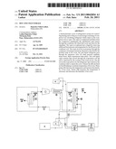
[0011]FIG. (1). is a schematic diagram of a vapors cycle refrigeration system.
DETAIL DESCRIPTION WITH REFERENCE TO THE ACCOMPANYING DRAWING
[0012]The embodiment described herein is in conjunction with vapor cycle refrigeration system in combination with thermodynamic cycle. Thermodynamic cycle provides superheating and super cooling to extend opposite ends of the regenerator to establish steady state conditions which increases the temperature ratio of the system. In turn the pressure ratio of the thermodynamic cycle is increased and the specification and the specific energy output improved. This expansion of the capability of thermodynamic machines for working in moderate temperature ranges is further utilized with system for achieving thermal gain for heating or cooling utilizing the ambient energy as a heat source as well.
[0013]Referring now to FIG. (1) there can be seen a thermodynamic cycle, a circulating refrigerant (like Freon, ammonia etc.) enters the compressor (1) as vapor. This vapor is compressed and then exists the compressor superheated. The superheated vapor passes through the condenser coil (2) which first cools and removes the superheat. The vapor is condensed into a liquid by removing additional heat pressure and temperature by using fan (5) across the condenser coil. The warm air in hot room passes through the condenser coil and gets heated up; this heat is absorbed by the products kept in hot room. The liquid refrigerant goes through the expansion valve (3) when its pressure suddenly drops down, flash evaporation takes place. This cold liquid vapor mixture then travels through the evaporation coil (4) and is vaporized by the cooling of the warm air (from the space being refrigerated) by a fan (6) across the evaporation coil. The resulting refrigerant vapor returns to the compressor inlet to complete the thermodynamic cycle. If the temperature of hot room goes beyond the required temperature the thermostat (7) switches on the exhaust fan (8) and the fresh air fan (9). If the atmosphere temperature is higher than hot room temperature then the thermostat gets activated and fresh air fan (9) gets switched off. At the same time the water pump (11) get starts and sprinkles water on both ends of the condenser coil. This water pump gets switched off once the atmospheric temperature becomes effectively less than the hot room temperature. If the humidity of the hot room goes down then the required, water pump starts with the help of the humidity stat (12). In case the water tank (13) is overhead, the water pump can be replaced by a solenoid valve for the water line. The thermostat which is capable of providing digital binary data to the transmitter specifying the set temperature and sensed or existing temperature so as to create a demand or trigger signal for heating or cooling for the rooms. A heater (14) at the condenser fan coil unit (2 and 5) is provided for heating the fresh product initially if necessary and to reduced humidity with the help of humidity stat (12). The main purpose of heater is to provide initial heat as required by the above said products to save from damage. Once the room temperature is set then heater is set OFF. When this system is installed for small commercial and domestic purpose there is no need of evaporation fan coil unit, condenser fan coil unit, water pump, fresh air fan and exhaust fan. Nor there is any need for the thermostat for hot compartment.
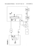
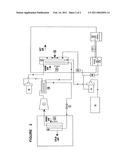
[0014]FIG. (2). is a schematic diagram of a vapors cycle refrigeration system using shell and tube type condenser (heat exchanger).
DETAIL DESCRIPTION WITH REFERENCE TO THE ACCOMPANYING DRAWING
[0015]Referring now to FIG. (2) there can be seen a thermodynamic cycle a circulating refrigerant (like Freon, ammonia etc.) enters the compressor (1) as vapor. This vapor is compressed and then exists the compressor superheated. The superheated vapor passes through the shell and tube type condenser (15) which first cools and removes the superheat by circulating water through tube of condenser and fan coil unit (2 and 5) with the help of condenser water pump (16). The vapor is condensed into a liquid by removing additional heat pressure and temperature by using shell and tube type condenser and this heat transfer to fan coil unit (2). The warm air in hot room passes through the coil and gets heated up with help of fan (5); this heat is absorbed by the products kept in hot room. The liquid refrigerant goes through the expansion valve (3) when its pressure suddenly drops down, flash evaporation takes place. This cold liquid vapor mixture then travels through the evaporation coil (4) and is vaporized by the cooling of the warm air (from the space being refrigerated) by a fan (6) across the evaporation coil.
[0016]The resulting refrigerant vapor returns to the compressor inlet to complete the thermodynamic cycle. If the temperature of hot room goes beyond the required temperature the thermostat (7) switches on the exhaust fan (8) and the fresh air fan (9). If the atmosphere temperature is higher than hot room temperature then the thermostat (10) gets on and switched off fresh air fan (9). At the same time the water pump (11) get starts and sprinkles water on both ends of the condenser coil. This water pump gets switched off once the atmospheric temperature becomes effectively less than the hot room temperature. If the humidity of the hot room goes down then the required, water pump starts with the help of the humidity stat (12). In case the water tank (13) is overhead, the water pump can be replaced by a solenoid valve for the water line. The thermostat which is capable of providing digital binary data to the transmitter specifying the set temperature and sensed or existing temperature so as to create a demand or trigger signal for heating or cooling for the rooms. A heater (14) at the hot room is provided for heating the fresh product initially if necessary. The main purpose of heater is to provide initial heat as required by the above said products to save from damage. Once the room temperature is set then heater is set OFF. When this system is installed for small commercial and domestic purpose there is no need of evaporation fan coil unit, condenser fan coil unit, water pump, fresh air fan and exhaust fan. Nor is there any need for the thermostat for hot compartment.
User Contributions:
comments("1"); ?> comment_form("1"); ?>Inventors list |
Agents list |
Assignees list |
List by place |
Classification tree browser |
Top 100 Inventors |
Top 100 Agents |
Top 100 Assignees |
Usenet FAQ Index |
Documents |
Other FAQs |
User Contributions:
Comment about this patent or add new information about this topic:
| People who visited this patent also read: | |
| Patent application number | Title |
|---|---|
| 20110045903 | METER SHIELD FOR USE WITH GAMING DEVICES |
| 20110045902 | EXTENSION COMPONENT FOR AUTHENTICATING GAME DATA |
| 20110045901 | INPUT/OUTPUT INTERFACE AND DEVICE ABSTRACTION |
| 20110045900 | SYSTEM, DEVICE AND METHOD FOR USING TIME-SENSITIVE TICKETS AS PLAYER AWARDS IN GAMING DEVICES |
| 20110045899 | SYSTEMS AND METHODS FOR MANAGING CARBON CREDIT DATA |
Images included with this patent application:
 |  |
 |
| Similar patent applications: | |
| Date | Title |
|---|---|
| 2010-01-21 | Latent cold storage device |
| 2013-04-04 | Liquid submersion cooled data storage or memory system |
| 2008-12-25 | Heating and cooling system |
| 2011-09-29 | Compact two sided cold plate with transfer tubes |
| 2011-12-01 | Heat conveyance and storage system |
| New patent applications in this class: | |
| Date | Title |
|---|---|
| 2016-01-07 | A modular liquid based heating and cooling system |
| 2015-04-16 | Methods and apparatuses for manipulating temperature |
| 2014-08-07 | Method for operating an hvac system |
| 2014-03-06 | Heat storage apparatus, air conditioning apparatus, and heat storage method |
| 2014-01-02 | Energy efficient thermostat |
| Top Inventors for class "Heat exchange" | |
| Rank | Inventor's name |
|---|---|
| 1 | Levi A. Campbell |
| 2 | Chun-Chi Chen |
| 3 | Tai-Her Yang |
| 4 | Robert E. Simons |
| 5 | Richard C. Chu |