Patent application title: VIBRATION TESTING DEVICE
Inventors:
Chao-Chien Lee (Tu-Cheng, TW)
Po-Yu Lin (Tu-Cheng, TW)
Ting-Hung Su (Tu-Cheng, TW)
Assignees:
HON HAI PRECISION INDUSTRY CO., LTD.
IPC8 Class: AG01M702FI
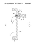
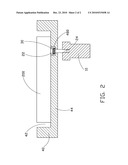
USPC Class:
73666
Class name: Vibrator table, platform, or other support having spring support
Publication date: 2010-12-23
Patent application number: 20100319458
Inventors list |
Agents list |
Assignees list |
List by place |
Classification tree browser |
Top 100 Inventors |
Top 100 Agents |
Top 100 Assignees |
Usenet FAQ Index |
Documents |
Other FAQs |
Patent application title: VIBRATION TESTING DEVICE
Inventors:
PO-YU LIN
CHAO-CHIEN LEE
TING-HUNG SU
Agents:
Altis Law Group, Inc.;ATTN: Steven Reiss
Assignees:
Origin: CITY OF INDUSTRY, CA US
IPC8 Class: AG01M702FI
USPC Class:
Publication date: 12/23/2010
Patent application number: 20100319458
Abstract:
A vibration testing device to test vibration strength and frequency
generated by an electronic device, includes a base, a vibration contact
member, a transmission member, and a resilient member attached to the
transmission member. The base includes a receiving space to receive the
electronic device and a receiving hole in communication with the
receiving space. The transmission member extends through the receiving
hole and is rigidly attached to the vibration contact member. During
testing, the electronic device directly abuts an end portion of the
transmission member so that the vibration strength and frequency
generated by the electronic device are directly transmitted to the
vibration contact member.Claims:
1. A vibration testing device to test vibration strength and frequency
generated by an electronic device, the vibration testing device
comprising:a base comprising a receiving space to receive the electronic
device and a receiving hole in communication with the receiving space;a
vibration contact member to obtain the vibration strength and frequency
generated by the electronic device;a transmission member extending
through the receiving hole and rigidly attached to the vibration contact
member; anda resilient member attached to the transmission member;wherein
during testing, the electronic device directly abuts an end portion of
the transmission member so that the vibration strength and frequency
generated by the electronic device are directly transmitted to the
vibration contact member.
2. The vibration testing device as recited in claim 1, wherein the transmission member comprises a transmission shaft and a transmitting portion located at a first end of the transmission shaft.
3. The vibration testing device as recited in claim 2, wherein the transmitting portion is a flange, wherein a diameter of the flange is greater than a diameter of the transmission shaft.
4. The vibration testing device as recited in claim 2, wherein the transmitting portion is a pin extending through the first end of the transmission shaft, wherein a length of the pin is greater than a diameter of the transmission shaft.
5. The vibration testing device as recited in claim 2, wherein the receiving hole comprises a locating hole, a through hole, and a step between the locating hole and the through hole, wherein a diameter of the locating hole is greater than a diameter of the through hole.
6. The vibration testing device as recited in claim 5, wherein the resilient member is fixed between the transmitting portion of the transmission member and the step of the receiving hole.
7. The vibration testing device as recited in claim 6, wherein the resilient member is a spring.
Description:
BACKGROUND
[0001]1. Technical Field
[0002]The present disclosure generally relates to a vibration testing device.
[0003]2. Description of Related Art
[0004]Electronic devices such as mobile phones and notebooks, for example, undergo a variety of tests to ensure quality. Frequently, an electronic device is mounted in a vibration testing device to determine whether vibration strength and frequency generated by the electronic device meet standard requirements. The testing device includes a base to receive the electronic device, and a vibration contact member directly attached to the base to obtain the vibration strength and frequency generated by the electronic device. However, since the vibration strength and frequency generated by the electronic device is transmitted to the vibration contact member via the base, some vibration energy generated by the electronic device is absorbed by the base during testing, resulting in improper test results.
[0005]Therefore, a need exists in the industry to overcome the described limitations.
BRIEF DESCRIPTION OF THE DRAWINGS
[0006]FIG. 1 is an assembled, schematic diagram of a vibration testing device of the disclosure; and
[0007]FIG. 2 is similar to FIG. 1, showing an electronic device received in the vibration testing device.
DETAILED DESCRIPTION
[0008]Referring to FIG. 1-FIG. 2, a testing device 100 determines whether vibration strength and frequency generated by an electronic device 200 such as a mobile phone, or a notebook, for example, meet standard requirements. The testing device 100 includes a vibration contact member 10, a transmission member 20, a resilient member 30, and a base 40 to receive the electronic device 200.
[0009]The base 40 defines a receiving space 42 to receive the electronic device 200, and a ladder-shaped receiving hole 48 located in a bottom of the receiving space 42 and in communication with the receiving space 42. The receiving hole 48 includes a locating hole 480, a through hole 482, and a step 484 between the locating hole 480 and the through hole 482. A diameter of the locating hole 480 is greater than a diameter of the through hole 482.
[0010]The vibration contact member 10 obtains the vibration strength and frequency generated by the electronic device 200, and defines a mounting hole 12. In the illustrated embodiment, the mounting hole 12 is threaded.
[0011]The transmission member 20 is rigidly connected to the vibration contact member 10, and includes a transmission shaft 24 and a supporting portion 22 located at a first end of the transmission shaft 24. In the illustrated embodiment, the supporting portion 22 can be a flange. A diameter of the flange is greater than a diameter of the transmission shaft 24, and less than a diameter of the locating hole 480.
[0012]The transmission shaft 24 includes a plurality of threads formed at a second end thereof apart from the supporting portion 22. The transmission shaft 24 extends through the receiving hole 48, and is fixed in the mounting hole 12 of the vibration contact member 10 to rigidly connect the transmission member 20 and the vibration contact member 10. In the illustrated embodiment, the transmission member 20 is a screw or a bolt.
[0013]Alternatively, the supporting portion 22 may be a pin extending through the first end of the transmission shaft 24. A length of the pin is greater than the diameter of the transmission shaft 24.
[0014]The resilient member 30 is attached to the transmission shaft 24 and located between the supporting portion 22 and the step 484 so that the supporting portion 22 tightly abuts the electronic device 200. In the illustrated embodiment, the resilient member 30 can be a spring.
[0015]During assembly, the resilient member 30 is attached to the transmission shaft 24. The second end of the transmission shaft 24 extends through the receiving hole 48 of the base 40 and is fixed in the mounting hole 12 of the vibration contact member 10. The electronic device 200 is received in the receiving space 42 of the base 40, and a vibration source of the electronic device (not shown) properly abuts the supporting portion 22 of the transmission member 20. Thus, the vibration contact member 10, the transmission member 20, the resilient member 30, the base 40, and the electronic device 200 are assembled. In this assembled state, the transmitting portion 22 of the transmission member 20 is located in the locating hole 480. The resilient member 30 is compressed. The vibration contact member 10 is overhung. That is, the vibration contact member 10 does not contact the base 40.
[0016]In use, the vibration strength and frequency generated by the electronic device 200 are directly transmitted to the vibration contact member 10 via the transmission member 20. During testing, the vibration energy generated by the electronic device 200 absorbed by the base 40 is substantially lessened, thus improving the accuracy of test results.
[0017]Because the transmission member 20 is rigidly connected to the vibration contact member 10, the vibration energy generated by the electronic device 200 absorbed by the transmission member 20 is substantially lessened, thus improving the accuracy of test results.
[0018]Because the vibration contact member 10 does not directly contact the base 40, the vibration generated by the base 40 is not transmitted to the vibration contact member 10, thus improving the accuracy of test results.
[0019]While an embodiment of the present disclosure has been described, it should be understood that it has been presented by way of example only and not by way of limitation. Thus the breadth and scope of the present disclosure should not be limited by the above-described exemplary embodiments, but should be defined only in accordance with the following claims and their equivalents.
User Contributions:
comments("1"); ?> comment_form("1"); ?>Inventors list |
Agents list |
Assignees list |
List by place |
Classification tree browser |
Top 100 Inventors |
Top 100 Agents |
Top 100 Assignees |
Usenet FAQ Index |
Documents |
Other FAQs |
User Contributions:
Comment about this patent or add new information about this topic:
Images included with this patent application:
 |  |
 |
| Similar patent applications: | |
| Date | Title |
|---|---|
| 2012-07-26 | Vibration detecting device |
| 2009-03-05 | Vibration test device |
| 2012-11-29 | Deformation testing device |
| 2010-03-25 | Tack adhesion testing device |
| 2012-07-26 | Hinge durability testing device |
| New patent applications in this class: | |
| Date | Title |
|---|---|
| 2009-10-01 | Handler comprising an acceleration device for testing electronic components |
| New patent applications from these inventors: | |
| Date | Title |
|---|---|
| 2011-03-24 | Camera module and testing method thereof |
| 2010-06-17 | Inspection device with rotatable adjustment members |
| 2009-11-12 | Connecting device for electronic testing system |
| Top Inventors for class "Measuring and testing" | |
| Rank | Inventor's name |
|---|---|
| 1 | Anthony D. Kurtz |
| 2 | Alfred Rieder |
| 3 | Johannes Classen |
| 4 | Manus P. Henry |
| 5 | Heewon Jeong |