Patent application title: STEERING WHEEL AND METHOD OF MANUFACTURING THE SAME
Inventors:
Joonmo Park (Hwaseong-Si, KR)
Assignees:
Kia Motors Corporation
Hyundai Motor Company
IPC8 Class: AB29C4514FI
USPC Class:
264255
Class name: To produce composite, plural part or multilayered article by separately molding different article portions sequential formation of portion on same mold or a preform surface
Publication date: 2010-11-04
Patent application number: 20100276838
Inventors list |
Agents list |
Assignees list |
List by place |
Classification tree browser |
Top 100 Inventors |
Top 100 Agents |
Top 100 Assignees |
Usenet FAQ Index |
Documents |
Other FAQs |
Patent application title: STEERING WHEEL AND METHOD OF MANUFACTURING THE SAME
Inventors:
Joonmo Park
Agents:
MORGAN, LEWIS & BOCKIUS LLP (SF)
Assignees:
Origin: SAN FRANCISCO, CA US
IPC8 Class: AB29C4514FI
USPC Class:
Publication date: 11/04/2010
Patent application number: 20100276838
Abstract:
A steering wheel includes a rim that is rotatable around a steering shaft.
The rim includes an armature; a first rim portion surrounding the
armature; and a second rim portion, covering part of the surface of the
first rim portion. A method of manufacturing a steering wheel includes
providing an armature; injection molding a first rim portion such that
the it surrounds the armature; injection molding a second rim portion;
and attaching the first and second rim portions such that the second rim
portion covers part of the surface of the first rim portion.Claims:
1. A method of manufacturing a steering wheel, comprising:providing an
armature;injection molding a first rim portion such that the first rim
portion substantially surrounds the armature;injection molding a second
rim portion; andattaching the first and second rim portions such that the
second rim portion covers the first rim portion at a part of a surface of
the first rim portion.
2. The method of claim 1, further comprising applying a decorative pattern to another part of the surface of the first rim portion.
3. The method of claim 1, further comprising attaching a cover to the second rim portion.
4. The method of claim 1, wherein attaching the first and second rim portions comprises mounting the second rim portion in at least one seat of the first rim portion.
5. The method of claim 4, wherein injection molding the second rim portion comprises injection molding a first shell and a second shell.
6. The method of claim 5, wherein each shell comprises a bend, wherein mounting the second rim portion in the seats comprises mounding each bend in one of the seats.
7. The method of claim 5, wherein the first shell comprises a groove, and the second shell comprises a protrusion, the method further comprising mounting the protrusion in the groove.
Description:
CROSS-REFERENCE TO RELATED APPLICATIONS
[0001]This application is a Divisional of U.S. patent application Ser. No. 12/167,006, filed Jul. 2, 2008, which claims priority to Korean Application Serial Number 10-2007-0131758, filed on Dec. 15, 2007, the entire contents of which is incorporated herein for all purposes by this reference.
FIELD OF THE INVENTION
[0002]The present invention relates to a decorative steering wheel and a method of manufacturing the steering wheel.
BACKGROUND OF THE INVENTION
[0003]Many steering wheel rims are made of expensive injection molded polyurethane. Some include portions with wood patterned surfaces.
SUMMARY OF THE INVENTION
[0004]A steering wheel includes a rim that is rotatable around a steering shaft. The rim includes an armature; a first rim portion surrounding the armature; and a second rim portion, covering part of the surface of the first rim portion.
[0005]Another part of the surface of the first rim portion may have a decorative pattern. A cover may be provided on the second rim portion. The first rim portion may have at least one seat in which the second rim portion is mounted. The second rim portion may be made of a first shell and a second shell. Each shell may have a bend that is mounted in one of the seats. The first shell may have a groove, and the second shell may have a protrusion mounted in the groove. A space may be defined between the two rim portions.
[0006]A method of manufacturing a steering wheel includes providing an armature; injection molding a first rim portion such that the it surrounds the armature; injection molding a second rim portion; and attaching the first and second rim portions such that the second rim portion covers part of the surface of the first rim portion.
BRIEF DESCRIPTION OF THE DRAWINGS
[0007]For better understanding of the nature and objects of the present invention, reference should be made to the following detailed description with the accompanying drawings, in which:
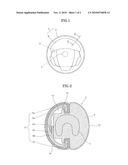
[0008]FIG. 1 is a front view of a steering wheel according to an exemplary embodiment;
[0009]FIG. 2 is a cross-sectional view taken along the line II-II of FIG. 1; and
[0010]FIG. 3 illustrates a manufacturing process of the steering wheel of FIGS. 1 and 2.
DETAILED DESCRIPTION OF THE PREFERRED EMBODIMENTS
[0011]Embodiments of the invention are described hereafter in detail with reference to the accompanying drawings.
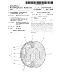
[0012]As shown in the figures, a steering wheel according to an embodiment of the invention includes a boss 1 that is connected with a steering shaft (not shown), a plurality of spokes 3 radially disposed around boss 1, and a rim 7 that is coaxial with boss 1, attached to the outer ends of spokes 3. Rim 7 is radially divided into an outer rim 9 and an inner rim 11 that join at the center of rim 7.
[0013]Outer rim 9 covers the entire circumference of a metallic armature 5 of rim 7 and may have a decorative pattern A, such as a wood pattern, on its surface. Outer rim 9 may be formed by injection molding of acrylonitrile butadiene styrene (ABS) resin around the surface of armature 5, and a film with the decorative pattern A may then be applied to the surface of outer rim 9.
[0014]Inner rim 11 is attached to outer rim 9. A soft pliable cover B may be attached to the surface of inner rim 11. Inner rim 11 may also be formed by injection molding of ABS resin. Cover B may be made of a soft material, such as leather or synthetic leather.
[0015]Outer rim 9 may include a seat 9a to hold inner rim 11 in place. Inner rim 11 may be made of a shell 13 that has a semi-arc cross section, and soft pliable cover B attached to the surface of shell 13.
[0016]Shell 13 is composed of an upper shell 13a and a lower shell 13b, each with one end supported by seats 9a. The other ends of the upper shell 13a and the lower shell 13b are connected to each other.
[0017]The upper shell 13a and the lower shell 13b may each have a bend 13c at one end that is placed in a respective one of the seats 9a. A protrusion 13d, or a groove 13e that is fitted on protrusion 13d, is provided at the other end.
[0018]A space S may be defined between the shell 13 and the outer rim 9, such that the total weight of rim 7 is reduced.
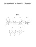
[0019]The above-described steering wheel may be made as follows, referring to FIG. 3. As shown in FIG. 3A, boss 1, spokes 3, and armature 5 are formed first. Next, as shown in FIG. 3B, outer rim 9 is injection molded onto armature 5. Next, as shown in FIG. 3C, wood pattern A is applied to at least a portion of outer rim 9, such as the outer circumferential edge in the illustration. Next, as shown in FIG. 3E, shell 13 is formed by injection molding upper and lower shells 13a, 13b. Next, as shown in FIG. 3F, cover B is attached onto the surface of shell 13. Next, as shown in FIG. 3D, the outer rim 9 is attached to the inner rim 11. Thereafter, the steering wheel is additionally provided with a variety of electrical parts and exterior materials for boss 1 and spokes 3.
[0020]While this invention has been described in connection with what is presently considered to be practical exemplary embodiments, it is to be understood that the invention is not limited to the disclosed embodiments, but, on the contrary, is intended to cover various modifications and equivalent arrangements included within the spirit and scope of the appended claims.
User Contributions:
comments("1"); ?> comment_form("1"); ?>Inventors list |
Agents list |
Assignees list |
List by place |
Classification tree browser |
Top 100 Inventors |
Top 100 Agents |
Top 100 Assignees |
Usenet FAQ Index |
Documents |
Other FAQs |
User Contributions:
Comment about this patent or add new information about this topic:
Images included with this patent application:
 |  |
 |
| New patent applications in this class: | |
| Date | Title |
|---|---|
| 2016-12-29 | Systems and methods for additive manufacturing processes |
| 2016-12-29 | Air freshener |
| 2016-09-01 | Fillers |
| 2016-07-07 | 3d printer for printing a plurality of material types |
| 2016-06-16 | Method and injection mold for producing an insert part having a plastic collar |
| New patent applications from these inventors: | |
| Date | Title |
|---|---|
| 2009-09-10 | Heated steering wheel using induction current |
| Top Inventors for class "Plastic and nonmetallic article shaping or treating: processes" | |
| Rank | Inventor's name |
|---|---|
| 1 | Shou-Shan Fan |
| 2 | Byung-Jin Choi |
| 3 | Yunbing Wang |
| 4 | Gene Michael Altonen |
| 5 | Sander Frederik Wuister |