Patent application title: Wireless, waterproof remote video weapon mounted sighting system, SmartSight
Inventors:
Matthew Charles Hagerty (Sonora, CA, US)
IPC8 Class: AF41G506FI
USPC Class:
89 4105
Class name: Training mechanisms motor operated by television monitoring
Publication date: 2010-10-14
Patent application number: 20100258000
Inventors list |
Agents list |
Assignees list |
List by place |
Classification tree browser |
Top 100 Inventors |
Top 100 Agents |
Top 100 Assignees |
Usenet FAQ Index |
Documents |
Other FAQs |
Patent application title: Wireless, waterproof remote video weapon mounted sighting system, SmartSight
Inventors:
Matthew Charles Hagerty
Agents:
STEFAN KIRCHANSKI
Assignees:
Origin: LOS ANGELES, CA US
IPC8 Class: AF41G506FI
USPC Class:
Publication date: 10/14/2010
Patent application number: 20100258000
Abstract:
A wireless waterproof remotely operated weapon mounted sighting system
consisting of three components: a weapon-mounted camera with power supply
and wireless connectivity, an operator borne CPU with wireless real time
image receiving, and HMD, for operator viewing of the combat environment.
The adjustable/zero-able sighting reticle, enables the operator precision
surgical strike capability from cover or concealment. The system enables
an operator to view surroundings plus aim and fire the weapon with
minimal operator exposure to hostile fire, as is the case in conventional
weapon sighting systems.Claims:
1-3. (canceled)
4. A remote weapon mounted viewing system comprising:a camera module mounted on a weapon for capturing an image of a field of view of the weapon;a wire for transmitting the image;an operator module for receiving the image transmitted by the camera module and for communicating the image wherein the operator module overlays a software generated sighting reticule on the image; anda head mounted display for receiving the image from the operator module and displaying the image to a weapon operator.
5. (canceled)
6. A remote weapon mounted viewing system comprising:a camera module mounted on a weapon for capturing an image of a field of view of the weapon;means for transmitting the image;an operator module for receiving the image transmitted by the camera module, for overlaying a software generated sighting reticule on the image and for communicating the image; anda head mounted display for receiving the image from the operator module and displaying the image to a weapon operator.
Description:
CROSS-REFERENCE TO PRIOR APPLICATIONS
[0001]This application is a non-provisional version of and claims priority and benefit from provisional application Ser. No. 60/594,792 filed 5 May 2005 which is hereby incorporated herein by reference.
BACKGROUND OF THE INVENTION
Area of the Art
[0002]The present invention is in the area of improved weapon sighting systems.
SUMMARY OF THE INVENTION
[0003]Since 1999, the invention, called "SmartSight" by the inventor, A Remote Video Weapon Mounted Sighting System has undergone continual and extensive research and development by the Principal Investigator, Mr. Matthew C. Hagerty of LandTec, Inc. For example, the device began as a wired system and is evolving into a wireless system. This application describes the wired system.
[0004]The Remote Weapon Mounted Sighting System consists of three primary components:
[0005]1). A Camera Module mounted on a weapon;
[0006]2). An Operator Module; and
[0007]3). A Heads Up/Mounted Display (HDM) worn by the weapon operator.
[0008]The Camera Module transmits an image to the Operator Module (via cables in this version). The Operator Module receives the image data from the Camera Module and overlays a sighting reticle on the video image which is then transmitted to the HMD, thereby providing a field of view to the weapon operator via the HMD.
[0009]This reticle can be aligned to the weapon, via the use of ergonomic controls on the Operator Module thus facilitating accurate target sighting by the operator aiming the weapon by means of the HMD. By separating the Camera Module from the operator and sighting reticle operator exposure to hostile fire is minimized, for example by allowing sighting or firing around corners without actually allowing any part of the operators body to extend around the corner.
DESCRIPTION OF THE FIGURES
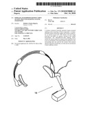
[0010]FIG. 1 is a diagrammatic view of a wired version of the system showing the Camera Module mounted on a weapon; and
DETAILED DESCRIPTION OF THE INVENTION
[0011]The following description is provided to enable any person skilled in the art to make and use the invention and sets forth the best modes contemplated by the inventor of carrying out his invention. Various modifications, however, will remain readily apparent to those skilled in the art, since the general principles of the present invention have been defined herein specifically to provide an improved remote video-based weapon sighting system.
[0012]The key components of the inventive device include:
[0013]1). A weapon mounted camera module, comprising a real time imaging device with auto-focus, auto-exposure, and zoom capability, and a system for communicating the weapon's field of view as captured by the camera module to 2). the waterproof operator module, an attached power source for the operator module and a waterproof HMD for allowing the weapon operator to view the field of view
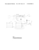
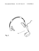
[0014]FIG. 1 shows the waterproof remote camera module 10 mounted on a weapon 12. The camera module 10 provides a viewing system that communicates real-time image data to the operator module (CPU module) 14 is attached to a power source (battery pack) 16 which is worn by the weapon operator. This combination significantly minimizes operator exposure to hostile fire. The operator module 14 provides a software generated sighting reticle that is overlaid on the weapon's field of view. The reticle can be calibrated and aligned with the weapon and receives real time image data from the camera module 10 using ergonomic control. In this way the real time image with the reticle is displayed by the wired HMD 18 so that the operator can see the weapon's field of view without being exposed to hostile fire. FIG. 2 shows more detail of the HDM 18. Normally, image encoding ensures that the Camera Module image data can be received by only one Operator Module. However, an alternate form of image encoding can ensure that the Camera Module image data may be received by a specific number of Operator Modules; for example, in the case of military intelligence and command and control.
[0015]Additional capability within the Operator Module can provide, by way of example and without limitation, target identification, target ranging data, GPS (global positioning system) coordinates, friend/foe determination and device status information.
[0016]The following claims are thus to be understood to include what is specifically illustrated and described above, what is conceptually equivalent, what can be obviously substituted and also what essentially incorporates the essential idea of the invention. Those skilled in the art will appreciate that various adaptations and modifications of the just-described preferred embodiment can be configured without departing from the scope of the invention. The illustrated embodiment has been set forth only for the purposes of example and that should not be taken as limiting the invention. Therefore, it is to be understood that, within the scope of the appended claims, the invention may be practiced other than as specifically described herein.
User Contributions:
comments("1"); ?> comment_form("1"); ?>Inventors list |
Agents list |
Assignees list |
List by place |
Classification tree browser |
Top 100 Inventors |
Top 100 Agents |
Top 100 Assignees |
Usenet FAQ Index |
Documents |
Other FAQs |
User Contributions:
Comment about this patent or add new information about this topic:
| People who visited this patent also read: | |
| Patent application number | Title |
|---|---|
| 20120173391 | MEDICATION INVENTORY MANAGEMENT |
| 20120173390 | SINGLE, MIXED-VIEW PRESENTATION OF RELATED PRODUCTS |
| 20120173389 | ESCROW ACCOMMODATION SYSTEM |
| 20120173388 | SYSTEM AND METHOD TO ASSOCIATE BROADCAST RADIO CONTENT WITH A TRANSACTION VIA AN INTERNET SERVER |
| 20120173387 | E-Commerce electronic data centrally distributed and collected |
Images included with this patent application:
 |  |
 |
| Similar patent applications: | |
| Date | Title |
|---|---|
| 2013-01-24 | Blast protected unit and system |
| 2011-09-01 | Apparatus and method for improved weapon configuration |
| 2012-01-19 | Remote digital firing system |
| 2010-09-02 | Bullet proof laminate and trauma pack |
| 2009-05-28 | Armor mounting system |
| New patent applications in this class: | |
| Date | Title |
|---|---|
| 2019-05-16 | Remote control gun |
| 2019-05-16 | Remote weapon control device and method for targeting and shooting multiple objects |
| 2016-06-09 | Apparatus for correcting ballistic errors using laser induced fluorescent (strobe) tracers |
| 2016-03-10 | External vision and/or weapon aiming and firing system for military land vehicles, military aircraft and military naval units |
| 2015-12-03 | Anti-sniper targeting and detection system |
| Top Inventors for class "Ordnance" | |
| Rank | Inventor's name |
|---|---|
| 1 | David L. Hunn |
| 2 | Jesus S. Gomez |
| 3 | Thomas Mann |
| 4 | John Carberry |
| 5 | Kevin M. Klatte |