Patent application title: DEVICE FOR PRODUCING AND PROPELLING STRING
Inventors:
Edward Joseph Piering, Iv (Gilbert, AZ, US)
Andrea Sue Piering (Gilbert, AZ, US)
IPC8 Class: AB65D8300FI
USPC Class:
2224021
Class name: With discharge assistant (e.g., impeller, pump, conveyer, movable trap chamber, etc.) fluid pressure valve actuated by nozzle or through valve outlet
Publication date: 2010-09-16
Patent application number: 20100230444
Inventors list |
Agents list |
Assignees list |
List by place |
Classification tree browser |
Top 100 Inventors |
Top 100 Agents |
Top 100 Assignees |
Usenet FAQ Index |
Documents |
Other FAQs |
Patent application title: DEVICE FOR PRODUCING AND PROPELLING STRING
Inventors:
Edward Joseph Piering, IV
Andrea Sue Piering
Agents:
Edward Piering
Assignees:
Origin: GILBERT, AZ US
IPC8 Class: AB65D8300FI
USPC Class:
Publication date: 09/16/2010
Patent application number: 20100230444
Abstract:
A device for propelling string may comprise a body usable to contain the
string, a nozzle, and a trigger that, when selected, causes the string to
be propelled out through the nozzle. The propelled string may be used to
identify potential trip wires.Claims:
1. A device for propelling string, the device comprising:a body usable to
contain the string;a nozzle; anda trigger that, when selected, causes the
string to be propelled out through the nozzle.
2. The device of claim 1, further comprising:a trigger guard flap covering the trigger, the trigger guard flap adapted to open and close so as to allow or prevent access to the trigger.
3. The device of claim 1, wherein an exterior of the body is covered by a flat paint of a muted color.
4. The device of claim 3, wherein the muted color comprises one of olive drab green and gray.
5. The device of claim 1, wherein the string is of a muted color.
6. The device of claim 5, wherein the muted color is tan, gray or olive green.
7. The device of claim 6, wherein the string comprises a glowing agent that is viewable through night vision goggles.
8. A method for detecting a trip wire on a ground, the method comprising:propelling a stream of string;determining whether the stream of string has fallen flat to the ground; andidentifying the presence or absence of the trip wire based on the determining.
9. The method of claim 8, wherein the stream of string is of a muted color.
10. The method of claim 9, wherein the stream of string comprise a glowing agent that is viewable through night vision goggles.
Description:
CLAIM OF PRIORITY
[0001]The present application claims the benefit of U.S. Provisional Patent Application No. 61/159,184, filed on Mar. 11, 2009, which is incorporated herein by reference in its entirety.
BACKGROUND OF THE INVENTION
[0002]The present invention generally relates to devices that produce string and, more specifically, to a device that produces and propels string that may be used to detect trip wires.
[0003]Members of law enforcement and the military may often be faced with booby traps that may be detonated via trip wires.
[0004]As can be seen, there is a need for a way to easily detect trip wires.
SUMMARY OF THE INVENTION
[0005]In one aspect of the present invention, a device for propelling string comprises a body usable to contain the string; a nozzle; and a trigger that, when selected, causes the string to be propelled out through the nozzle.
[0006]In another aspect of the present invention, a method for detecting a trip wire on a ground comprises propelling a stream of string; determining whether the stream of string has fallen flat to the ground; and identifying the trip wire based on the determining.
[0007]These and other features, aspects and advantages of the present invention will become better understood with reference to the following drawings, description and claims.
BRIEF DESCRIPTION OF THE DRAWINGS
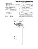
[0008]FIG. 1 shows a perspective view of a trip wire detection device in accordance with an embodiment of the present invention;
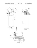
[0009]FIG. 2 shows a side view of the trip wire detection device of FIG. 1; and
[0010]FIG. 3 shows a detailed side view of the trip wire detection device of FIG. 1.
DETAILED DESCRIPTION OF THE INVENTION
[0011]The following detailed description is of the best currently contemplated modes of carrying out exemplary embodiments of the invention. The description is not to be taken in a limiting sense, but is made merely for the purpose of illustrating the general principles of the invention, since the scope of the invention is best defined by the appended claims.
[0012]Various inventive features are described below that can each be used independently of one another or in combination with other features.
[0013]Broadly, embodiments of the present invention generally provide a trip wire detection device that may be operable to produce and propel string. The produced and propelled string may hang from trip wires of booby traps, thereby helping a user of the device to easily spot and avoid the trip wires, such as at nighttime. Further, the device may be designed to reflect a minimal amount of light while still being easily visible to the user even in the dark, thereby minimizing the chances that the user's position may be exposed to enemy forces during battle.
[0014]Referring now to FIGS. 1-3, a trip wire detection device 10 may comprise a body 12, a top 20, a trigger 14, a trigger guard flap 16, and a nozzle 18. The device 10 may be approximately six inches in height and approximately three inches in diameter. The body 105 may be a container, such as a can or any other suitable container, and may store strings 24, such as aerosol strings as well as propellant, such as compressed air, for propelling the strings 24. The top 20 may include the trigger 14, the trigger guard flap 16, and the nozzle 18. The trigger 14, when depressed or otherwise selected, may cause the strings 24 contained within the body 12 of the device 10 to be produced and propelled out of the device 10 via the nozzle 18. To prevent accidental discharge of the strings 24, the trigger guard flap 16 may be a thumb flap that covers the trigger 14 and that may flip down to prevent the trigger 14 from being accidentally activated. The trigger guard flap 16 may also flip up in order to provide access to the trigger 14. The trigger guard flap 16 may pivot on the top 20 via an axle 22 about which it may pivot in order to flip up or down as may be needed.
[0015]To decrease the chances that the position of the user of the device 10 may be exposed during use of the device 10, the device 10 may be designed to blend into low-visibility conditions by minimizing the amount of light reflected off of the device 10. To that end, the body 12 of the device 10 may be comprised of metal, such as aluminum, and the exterior of the body 12 may be painted with a flat paint in a muted color, such as olive drab green or gray. Further, the strings 24 may have a muted color, such as a tan, gray or olive green color, so that the strings 24 may be difficult to see with the naked eye by blending with the surrounding environment, and may contain a glowing agent within the strings 24 that may allow the strings 24 to be viewable through night vision goggles in low-light conditions. Such a glowing agent may cause the strings 24 to be more easily identifiable, such as by causing the strings 24 to glow, when viewed through night vision goggles, while the glowing agent may remain invisible or nearly invisible and may not cause the strings 24 to increase in visibility when viewed with the naked eye without the night vision goggles.
[0016]In use, a user may come upon an area that may have a potential trip wire hazard. To identify the potential trip wire hazard, the user may hold the device 10 towards an intended path for the user, raise the trigger guard flap 16, aim the device 10 approximately seven feet in the air horizontally to the ground, and depress the trigger 14. While the trigger 14 is depressed, a continuous stream of strings 24 may flow from the nozzle 18 of the device 10. After a short burst, the strings 24 may fall towards the ground. If the strings 24 fall flat to the ground, it may indicate that the strings 24 are not tied up on trip wires of the trip wire hazard. Alternatively, if any strings 24 do not fall flat onto the ground, as seen by the user either with the naked eye or through night vision goggles, those strings 24 may indicate that they are hung on trip wires of the trip wire hazard, thereby identifying the trip wire hazard. If the user does not detect the potential trip wire hazard, the user may then advance ten to fifteen feet and repeat the process until an entire path of the user has been rendered clear. Once the user has finished the process of detecting the potential trip wire hazard, the user may flip the trigger guard flap 16 down and store the device 10 in a standard flash bang pouch.
[0017]To make an embodiment of the present invention, the body 12 may be filled with a mixture of the strings 24 and propellant. The top 20 may then be affixed to the body 12. The strings may comprise a synthetic resin in a mixture with a solvent along with a plasticizer for the resin while the body may comprise an aerosol can. When the trigger 14 is depressed, the propellant may cause the synthetic resin along with the plasticizer to mix and be propelled through the nozzle. When the synthetic resin and the plasticizer hits the air after exiting the nozzle 18, the synthetic resin and the plasticizer may then form a skin and thereby become a foam or aerosol string 24.
[0018]It should be understood, of course, that the foregoing relates to exemplary embodiments of the invention and that modifications may be made without departing from the spirit and scope of the invention as set forth in the following claims.
User Contributions:
comments("1"); ?> comment_form("1"); ?>Inventors list |
Agents list |
Assignees list |
List by place |
Classification tree browser |
Top 100 Inventors |
Top 100 Agents |
Top 100 Assignees |
Usenet FAQ Index |
Documents |
Other FAQs |
User Contributions:
Comment about this patent or add new information about this topic:
| People who visited this patent also read: | |
| Patent application number | Title |
|---|---|
| 20100231143 | OPTICAL INTEGRATING CAVITY LIGHTING SYSTEM USING MULTIPLE LED LIGHT SOURCES WITH A CONTROL CIRCUIT |
| 20100231133 | APPARATUS FOR CONTROLLING SERIES-CONNECTED LIGHT EMITTING DIODES |
| 20100231129 | Ceramic discharge lamp and method of manufacturing ceramic discharge lamp |
| 20100231128 | PLASMA DISPLAY PANEL |
| 20100231125 | ORGANIC LIGHT EMITTING DEVICE TO EMIT IN NEAR INFRARED |
Images included with this patent application:
 |  |
| Similar patent applications: | |
| Date | Title |
|---|---|
| 2012-12-06 | One-way valve for discharge regulation in tubes, tube with such a one-way valve and method for manufacturing such a one-way valve |
| 2010-03-18 | Device for grains dosing with air sealing |
| 2011-03-24 | Device for dispensing a liquid in a tank |
| 2012-06-07 | Air collecting and expelling amusement device |
| 2012-11-01 | Device for dispensing a flowable material |
| New patent applications in this class: | |
| Date | Title |
|---|---|
| 2018-01-25 | Device with co-extruded body and flexible inner bladder and related apparatus and method |
| 2016-12-29 | Ring for a device for dispensing a fluid product |
| 2016-12-29 | Compressible valve for a pressurized container |
| 2016-06-30 | Aerosol plastic container made from an isosorbide containing copolyester and aerosol dispenser comprising said aerosol plastic container |
| 2016-06-02 | Aerosol spray device |
| Top Inventors for class "Dispensing" | |
| Rank | Inventor's name |
|---|---|
| 1 | Nick E. Ciavarella |
| 2 | John J. Mcnulty |
| 3 | Robert L. Quinlan |
| 4 | Andrew Jones |
| 5 | Heiner Ophardt |