Patent application title: ACTUATING DEVICE FOR TWO PARALLEL ROTATING CAMSHAFTS
Inventors:
Falk Schneider (Korntal-Munchingen, DE)
IPC8 Class: AF01L134FI
USPC Class:
123 9015
Class name: Internal-combustion engines poppet valve operating mechanism with means for varying timing
Publication date: 2010-05-27
Patent application number: 20100126443
Inventors list |
Agents list |
Assignees list |
List by place |
Classification tree browser |
Top 100 Inventors |
Top 100 Agents |
Top 100 Assignees |
Usenet FAQ Index |
Documents |
Other FAQs |
Patent application title: ACTUATING DEVICE FOR TWO PARALLEL ROTATING CAMSHAFTS
Inventors:
Falk Schneider
Agents:
RADER, FISHMAN & GRAUER PLLC
Assignees:
Origin: BLOOMFIELD HILLS, MI US
IPC8 Class: AF01L134FI
USPC Class:
123 9015
Publication date: 05/27/2010
Patent application number: 20100126443
Abstract:
The invention relates to an actuating device for two parallel rotating
camshafts. The aim of the invention is to optimize the installation space
required for such a device. For this purpose, both camshafts (3, 4)
consist of two shafts that rotate concentrically one inside the other and
that can be rotated in relation to each other. On one end of the
camshafts (3, 4), one of the two shafts (3', 3''; 4', 4'') is driven by
the crankshaft (1) via a single, directly acting force-transmitting
element (2). A phase adjuster (5) is provided on the other end of the
camshafts (3, 4) and allows the simultaneous adjustment of both shafts
(3'', 4''; 3', 4') in relation to each other by means of a
force-transmitting element (6) acting on the phase adjuster (5). Said
force-transmitting element connects a region of a camshaft (3, 4) that is
firmly connected to an inner or outer shaft (3'', 4''; 3', 4') to an
inner or outer shaft (3'', 4''; 3', 4'), to be adjusted accordingly, of
the other camshaft (4, 3) in a force-transmitting manner.Claims:
1. An actuating device for two parallel rotating camshafts comprising:at
least one inner camshaft having a first end and an opposite second end;
andat least one outer camshaft having a first end and an opposite second
end, wherein the inner and outer camshafts are arranged concentrically,
one inside the other, and the inner and outer camshafts rotate with
respect to each other, wherein the inner shaft and the outer shaft
include at least one of a first cam connected to the outer shaft and at
least one of a second cam connected to the inner shaft,wherein at least
one of the inner and outer camshaft first and second ends, is driven by a
crankshaft; andat least one phase adjuster is provided at the other
opposite first or second end of the inner and outer camshaft, and
providing for selective simultaneous adjustment of both the inner and
outer shaft, by a force-transmitting element which acts on the phase
adjuster, wherein the force-transmitting element connects to a firmly
connected region of at least on of the inner and outer camshafts to be
adjusted accordingly, in a force-transmitting manner.Description:
[0001]The invention relates to an actuating device for two parallel
rotating camshafts according to the preamble of the patent claim 1.
[0002]Such actuating devices are known from U.S. Pat. No. 5,417,185 A and EP 1 614 867 A1.
[0003]In each of these actuating devices, the phase adjuster is located at the same end of the two camshafts at which end they are driven by the crankshaft.
[0004]In this region of an internal combustion engine, confined installation conditions can exist by means of which it can be difficult to accommodate the generic phase adjuster therein. This applies in particular to engines which were originally designed for a camshaft actuating device without a phase adjuster and which are intended to be retrofitted with a phase adjuster and individually adjustable camshafts.
[0005]The invention is concerned with the problem to provide a solution here which can be realized as simple as possible by means of a design of a generic actuating device according to the characterizing features of the patent claim 1.
[0006]The invention is based here on the general idea to arrange the phase adjuster in the generic camshaft device in such a manner that the typical chain drive, which is actuated by the crankshaft as the drive source, can be configured or remain, respectively, in a constructionally simple manner as it is used for camshafts which are not adjustable by means of a phase adjuster.
[0007]In the only drawing
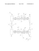
[0008]FIG. 1 shows a schematic structure of an actuating device according to the invention.
[0009]By means of crankshaft 1, which is drawn only by a dot-dashed line, two camshafts arranged parallel to one another, namely a first camshaft 3 and a second camshaft 4, are driven via a chain 2 as a force-transmitting element.
[0010]The two camshafts 3, 4 each consist of two shafts which are arranged concentrically one inside the other and which rotate with respect to each other, namely of an outer shaft 3' and an inner shaft 3'' for the first camshaft 3, and an outer shaft 4' and an inner shaft 4'' for the second camshaft. The outer shaft cams 3''', 4''' and the inner shaft cams 3IV and 4IV are each firmly connected with an inner shaft and an outer shaft 3'', 4''; 3', 4', respectively.
[0011]By means of the chain 2 as a force-transmitting element, each of the outer shafts 3', 4' of the camshafts 3, 4, respectively, are driven.
[0012]The inner shafts 3'', 4'' are rotatably mounted inside the outer shafts 3', 4'. To be able to rotate the two inner shafts 3'', 4'' synchronously with respect to the outer shafts 3', 4', and in particular during engine operation, at one of the camshafts 3, 4, namely the second camshaft 4, at its end which is opposite to the end with which the chain 2 engages, a phase adjuster 5 is provided which is known per se with respect to its function.
[0013]This phase adjuster 5 has two regions which can be rotated with respect to each other, one of which is firmly connected with the inner shafts 3'' and 4''. By actuating this phase adjuster 5, a relative rotation of the inner shaft 4'' with respect to the outer shaft 4' of the camshaft 4 takes place. To achieve a synchronous drive of the inner shafts 3'', 4'', a force-transmitting element 6 configured, for example, as a chain, connects the region of the phase adjuster 5 firmly connected to the inner shaft 4'' with the inner shaft 3'' of the camshaft 3.
[0014]The camshafts 3, 4 are rotatably mounted in bearings 7 within the engine.
[0015]All features illustrated in the description and in the following claims can be essential for the invention, individually as well as combined with one another in any form.
User Contributions:
comments("1"); ?> comment_form("1"); ?>Inventors list |
Agents list |
Assignees list |
List by place |
Classification tree browser |
Top 100 Inventors |
Top 100 Agents |
Top 100 Assignees |
Usenet FAQ Index |
Documents |
Other FAQs |
User Contributions:
Comment about this patent or add new information about this topic:
| People who visited this patent also read: | |
| Patent application number | Title |
|---|---|
| 20100130259 | MOBILE TERMINAL WITH IMAGE PROJECTOR AND METHOD OF STABILIZING IMAGE THEREIN |
| 20100130258 | Gravity axis determination apparatus and mobile terminal apparatus using the same |
| 20100130257 | MOBILE TERMINAL AND METHOD OF CONTROLLING THE MOBILE TERMINAL |
| 20100130256 | METHOD FOR PREVIEWING OUTPUT CHARACTER AND ELECTRONIC DEVICE |
| 20100130255 | METHOD AND APPARATUS FOR STORING A SOFTWARE LICENCE |
Images included with this patent application:
 |  |
 |
| Similar patent applications: | |
| Date | Title |
|---|---|
| 2012-06-14 | Device for adjusting the rotational angular position of a cam shaft |
| 2012-03-22 | Anti-cogging apparatus and methods for reducing cogging of rotating shaft |
| 2012-08-23 | Device for variably adjusting the control times of gas exchange valves of an internal combustion engine |
| 2008-11-27 | Apparatus for preventing leakage across rotor vanes in a vane-type camshaft phaser |
| 2011-08-18 | Securing device for installing a rocker arm |
| New patent applications in this class: | |
| Date | Title |
|---|---|
| 2018-01-25 | Split axial cam shifting system variable valve actuation functions |
| 2016-12-29 | Motor vehicle, control unit and method for controlling a phase angle of a camshaft |
| 2016-12-29 | Valve timing control device for internal combustion engine and controller for valve timing control device |
| 2016-12-29 | Apparatus for opening and closing channel |
| 2016-12-29 | Rotation control apparatus of cvvt |
| New patent applications from these inventors: | |
| Date | Title |
|---|---|
| 2013-01-24 | Camshaft and associated cam |
| 2013-01-24 | Camshaft and associate manufacturing method |
| 2012-12-20 | Internal combustion engine |
| 2012-10-11 | Camshaft |
| 2012-02-16 | Camshaft |
| Top Inventors for class "Internal-combustion engines" | |
| Rank | Inventor's name |
|---|---|
| 1 | Ross Dykstra Pursifull |
| 2 | Gopichandra Surnilla |
| 3 | Joseph Norman Ulrey |
| 4 | Thomas G. Leone |
| 5 | Chris Paul Glugla |