Patent application title: Urea Monitoring And Replenishment Scheduling of Vehicles
Inventors:
Patrick E. Charbonneau (South Barrington, IL, US)
Assignees:
International Truck Intellectual Property Company, LLC
IPC8 Class: AF01N900FI
USPC Class:
60286
Class name: Internal combustion engine with treatment or handling of exhaust gas by means producing a chemical reaction of a component of the exhaust gas condition responsive control of heater, cooler, igniter, or fuel supply of reactor
Publication date: 2010-05-13
Patent application number: 20100115925
Inventors list |
Agents list |
Assignees list |
List by place |
Classification tree browser |
Top 100 Inventors |
Top 100 Agents |
Top 100 Assignees |
Usenet FAQ Index |
Documents |
Other FAQs |
Patent application title: Urea Monitoring And Replenishment Scheduling of Vehicles
Inventors:
Patrick E. Charbonneau
Agents:
International Truck Intellectual Property Company,
Assignees:
International Truck Intellectual Property Company LLC
Origin: WARRENVILLE, IL US
IPC8 Class: AF01N900FI
USPC Class:
60286
Publication date: 05/13/2010
Patent application number: 20100115925
Abstract:
Urea supply information with is integrated with vehicle location, routing
and urea consumption information to generate driver guidance for
obtaining urea resupply or, at a minimum, automatically generating orders
to position supplies of urea at a target location.Claims:
1. For a vehicle equipped with an internal combustion engine and an
exhaust after-treatment system using urea, a urea replenishment
management system comprising:a position determining unit installed on the
vehicle;a urea tank and urea tank fill level sensor;a remote server
having access to geographic information including locations providing
urea replenishment for vehicles;a body computer installed on the vehicle
and coupled to receive data from the position determining unit and the
urea tank fill level sensor and to receive inputs from and display
information on driver input/output interface;a communications system link
between the remote server and the body computer;the remote server being
responsive to vehicle location and urea tank fill levels for providing
urea supply locations over the communications system link to the body
computer for display on the driver input/output interface.
2. The urea replenishment management system of claim 1, further comprising:the remote server further providing analysis of available urea replenishment locations with vehicle location, vehicle destination and routing information to generate driver guidance to the driver for obtaining urea resupply for display on the driver input/output interface.
3. The urea replenishment management system of claim 2, further comprising:the remote server being further programmed to generate orders for delivery of urea to locations accessible from a vehicle's projected route.
4. The urea replenishment management system of claim 3, further comprising:the remote server tracking fuel consumption against urea tank fill levels and estimating vehicle operating range based on urea reserves.
5. The urea replenishment management system of claim 4, further comprising the body computer providing for removing, adding and reordering a destination list.
6. A method of managing replenishment of urea on a diesel engine equipped vehicle using urea for exhaust after treatment, the method comprising the steps of:periodically updating a list of destinations for the vehicle;determining routes for the truck from the list of destinations and a geography information system;monitoring urea tank fill levels and estimating remaining range of vehicle operation as a function of urea consumption and reserves; andgenerating for display a list of supply depots keyed to the determined routes for the vehicle driver.
7. A method of managing replenishment of urea as claimed in claim 6, comprising the additional step of:responsive to indication that no supply depot is acceptable, ordering delivery of a supply of urea to a designated location for use in replenishing the vehicle.
8. A data integration system for motor vehicle urea replenishment servicing, comprising:a central database of urea service facilities located across a geographic area and availability of urea at the urea service facilities;a plurality of vehicles requiring periodic urea servicing traversing the geographic area; anda communication system linking the plurality of vehicles to the central database allowing the vehicles to indicate a need for urea replenishment and the central database to distribute to the vehicles individualized lists of prospective urea service facilities.
9. A data integration system as claimed in claim 8, further comprising:the plurality of vehicles including data processing facilities allowing generation and updating of a list of destinations.
10. A data integration system as claimed in claim 9, further comprising:the central database providing routes for each vehicle based on the list of destinations and responsive to forecast need for urea replenishment.
11. A data integration system as claimed in claim 10, further comprising: means for ordering positioning of urea for a vehicle.
Description:
BACKGROUND OF THE INVENTION
[0001]1. Technical Field
[0002]The invention relates to vehicle telematics and more particularly to providing routing and scheduling of vehicles for replenishment of urea required for exhaust after-treatment on some diesel engine equipped vehicles.
[0003]2. Description of the Problem
[0004]Diesel engine equipped highway vehicles will, beginning in 2010, be required to meet tightened emission standards in the United States. One after-treatment technology developed to reduce emissions from diesel engines, selective catalytic reduction (SCR), requires urea. The United States Environmental Protection Agency has mandated that vehicles be disabled if the diesel pollution control system is not operative. Exhaustion of the on-board urea supply on SCR equipped vehicles would be a condition requiring making a vehicle inoperative.
[0005]There is a need to insure the reasonable availability of urea to allow operators of commercial vehicles to replenish on board supplies of urea where little extant urea distribution infrastructure exists. Barton and Lonsdale writing for the Diesel Engine Emissions Reduction (DEER) conference of 24-28 Aug. 2003 stated that urea costs would be dominated by distribution costs and not primarily be production or raw material costs. With urea consumption in liquid measurement terms equaling about 5% of fuel consumption a 25 gallon urea tank would support a range of 3,250 miles on a vehicle achieving an average fuel economy of 6.5 miles per gallon, typical for a heavy duty truck. Replenishment of urea at locations close to production facilities to minimize its cost promises some cost savings. However, it is possible that development of a urea distribution system is being depressed by the possibility that technological developments may render obsolete urea based SCR systems.
[0006]If a vehicle must be removed from service awaiting replenishment of urea its owner may incur substantial costs due to unavailability of the vehicle and the need to arrange an emergency delivery of urea to the vehicle. It would be advantageous to anticipate the need to replenish the supply, and be able to efficiently route the vehicle near existing supplies, pre-schedule replenishment and/or preposition supplies to minimize down time of vehicles.
[0007]The assignee of the present invention operates the International Aware Vehicle Intelligence system, an enhanced vehicle telematics system providing vehicle performance tracking, diagnostic functions and mapping capabilities through a mixture of on-board and off-board electronics. Owners of vehicles may subscribe to the system. The off-board electronics include wireless communications systems and the global positioning system (GPS).
SUMMARY OF THE INVENTION
[0008]For a vehicle equipped with an internal combustion engine and an SCR exhaust after-treatment system using urea, the invention integrates available urea supply information with vehicle location, routing and urea consumption information to generate driver guidance for obtaining urea resupply or, at a minimum, automatically generating orders to position supplies of urea at a target location. A positioning information system provides current vehicle location. The vehicle tracks fuel consumption and urea tank fill levels. This data is reported over a communication link to a central data processing server which can access current and projected availability of urea along likely routes and return the data to the driver of the vehicle.
[0009]Additional effects, features and advantages will be apparent in the written description that follows.
BRIEF DESCRIPTION OF THE DRAWINGS
[0010]The novel features believed characteristic of the invention are set forth in the appended claims. The invention itself however, as well as a preferred mode of use, further objects and advantages thereof, will best be understood by reference to the following detailed description of an illustrative embodiment when read in conjunction with the accompanying drawings, wherein:
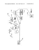
[0011]FIG. 1 is a schematic of a telematics systems adapted for data condition data collection and integration system for enhancing commercial vehicle in service time.
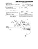
[0012]FIG. 2 is a block diagram of a vehicle controller area network control system adapted for use in the data collection and integration system of FIG. 1.
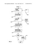
[0013]FIG. 3 is a simplified flow chart related to vehicle identification and routing for urea replenishment.
DETAILED DESCRIPTION OF THE INVENTION
[0014]Referring now to the figures and in particular to FIG. 1, a generalized vehicle telematics system 100 emphasizing central support for vehicle management is illustrated. Vehicle telematics system 100 may be implemented using one, or more typically, a large plurality of vehicles represented by vehicle 102, which communicate with a manufacturer's or vehicle operator server 114 using any convenient means. The linkages are typically implemented over a cellular telephone link 108 to link with a cellular base station 112 or short range RF link.
[0015]Vehicle 102 includes an electronic control system based on a controller area network (CAN) system 104. Controller area network system 104 links numerous controllers onboard commercial vehicle 102 for data communication and allows central activation and control of remote data communications services as through cellular phone link 106 and use of services such as global positioning using a global positioning unit 108 reading GPS satellites 110.
[0016]Cell phone base station 112 is linked by land lines including, if advantageous, internet services, for the transfer of data from cell phone link 108 to a server 114. The data from the vehicle 102 can include, as set forth in detail below, information relating to engine loading, extreme brake use and other vehicle operating variables collected by the CAN system 104. Records forwarded from vehicle 102 are time, date, location and mileage stamped. Data can be forwarded from a vehicle over a cell phone link by connection 115 (such as short range RF or direct hand wire connection) to server 114 which accesses statistical processing services 124 for determination of projected duration of the urea supply based on its historical relation to fuel consumption for the vehicle 102. Data bases 128 including geographic information systems can be accessed to project fuel consumption based on routing of the vehicle (if available) and to update the list of urea supply points for uplink to the driver on board the vehicle 102. Server 114 maintains a website with pages for each vehicle 102 which may include a map with the vehicle's location and notations as to the locations of supplies of accessible urea supplies, emphasizing supplies located along the vehicle's projected route.
[0017]Server 114 maintains databases of vehicle statistics indexed by mileage on databases 128 and the availability of urea at geographically distributed urea service facilities 190. These records allow in urea use trends to be detected by comparison operations 124 with the results being placed on a secured page on website 122 for the use of management.
[0018]Referring now to FIG. 2, the features of a controller area network system 104 such as used on vehicle 102 are set out. Controller area network 104 has as a foundational element a programmable body computer 230 based on a microprocessor 272 and memory 274. Memory 274 may in turn include both volatile and non-volatile sections (not shown). Microprocessor 272 communicates with other parts of the programmable body computer 230 over a conventional bus. Among the other parts of the computer are input/output devices for handling network communications including first (public) and second (proprietary) controller area network (CAN) interfaces 250. A vehicle electrical power system 245 provides power to all of the components. Microprocessor 272 is directly connected to input and output devices installed in the cab of a vehicle.
[0019]CAN system 104 includes two distinct controller area networks based on a first bus using the public codes of the Society of Automotive Engineers (SAE) standard for J1939 networks and a second using proprietary codes, the definition of which is allowed under the standard. By "proprietary" it is meant only that standard format J1939 data block may be defined as desired by an OEM. The public bus connects first CAN interface 250 to a plurality of system controllers including an instrument and switch bank 212, a gauge cluster 214, an anti-lock brake system controller 219, a transmission controller 216 and an engine controller 220. Any of these controllers may in turn be connected to one or sensors of packages of sensors associated with a specific controller. For example, ABS controller 219 collects data from sensors 231 which include at least the wheel speed sensors used for determining skidding. Transmission controller 216 may track transmission fluid levels or include a drive shaft tachometer from drive train sensors 217. The most important collection of sensors though is the engine sensor package 221 connected to the engine controller 230 which includes an engine tachometer, an air intake temperature gauge (providing a reasonable reading of ambient temperature), coolant temperatures, and engine oil temperature, level and dielectric constant readings. The engine controller 220 provides a convenient point of connection for a urea level sensor 270 which monitors urea tank 271 fill levels.
[0020]Microprocessor/body computer 230 is itself a controller and can be used for direct monitoring of vehicle components, such as the working status of lights connected to an electrical system 233. Body computer 230 operates as a controller on two distinct CAN busses. Devices using proprietary codes are coupled to the second bus and here include a GPS receiver unit 242, a specialized controller 244 and a cell-phone transceiver unit 240, each of which include a CAN interface 250. Transceiver unit 240 additionally a microcontroller 241, a modulating unit 243 and a transceiver unit 245 connected to an antenna 247. Data collected by body computer 230, mostly over the first CAN network, are transferred using code blocks defined for that function over the second CAN network to cell phone unit 240 where it is used to modulate a carrier for transmission. Body computer 230 has access to data such as mileage and to clock information, fuel consumption and urea tank fill levels, as well as GPS data, allowing the body computer to stamp data records as to time, date, mileage and location relating to sensor reading falling outside of normal reading categories or otherwise meeting some criteria defined by the operator. This is based on a need or desire to maintain the record for use of the central server 114.
[0021]Referring to FIG. 3, a flow chart is used for describing operations at the vehicle and server level supporting the system and process of the present invention. Upon start of a vehicle, and recurring periodically thereafter vehicle 102 location is obtained from a GPS unit 303 or equivalent (step 301). At step 305 the vehicle's destination list is updated. GPS location information may be used to key removal of destinations from the top of the list and follow on destinations may be reordered and added. With each update of the destination list projected routes are changed (step 307). A geographic information system 309 may be accessed to produce routes including considerations such as detours or even instant traffic conditions. It is conceivable on some vehicles that the routing and destination ordering may be made interactive, based on availability of routes and congestion considerations. The projection 311 of urea consumption may be based on projected fuel economy for the selected routes and a range estimated based on projected usage and the current urea tank fill level. Once this is done urea replenishment options may be generated for display to the driver (step 313) emphasizing urea service facilities 190 located along projected routes. If the options are not favorable, pre-staging of urea at a urea service facility 190 may be considered (step 315) and positioning (step 317) of supplies made.
[0022]Those skilled in the art will now appreciate that alternative embodiments of the invention can exist. While the invention is shown in one of its forms, it is not thus limited but is susceptible to various changes and modifications without departing from the spirit and scope of the invention.
User Contributions:
comments("1"); ?> comment_form("1"); ?>Inventors list |
Agents list |
Assignees list |
List by place |
Classification tree browser |
Top 100 Inventors |
Top 100 Agents |
Top 100 Assignees |
Usenet FAQ Index |
Documents |
Other FAQs |
User Contributions:
Comment about this patent or add new information about this topic:
Images included with this patent application:
 |  |
 |  |
| New patent applications in this class: | |
| Date | Title |
|---|---|
| 2018-01-25 | Electric exhaust-gas catalytic converter, vehicle and method for operating an electric exhaust-gas catalytic converter |
| 2018-01-25 | Exhaust system for a compression ignition engine comprising a water adsorbent material |
| 2017-08-17 | Urea mixer |
| 2017-08-17 | Method and apparatus for controlling an internal combustion engine coupled to an exhaust aftertreatment system |
| 2017-08-17 | Scr after-treatment of engine exhaust gas |
| Top Inventors for class "Power plants" | |
| Rank | Inventor's name |
|---|---|
| 1 | Gabriel L. Suciu |
| 2 | Patrick Benedict Melton |
| 3 | Eugene V. Gonze |
| 4 | Thomas Edward Johnson |
| 5 | Jan Hodgson |