Patent application title: Attachment device for attaching slinging or lashing means
Inventors:
Reinhard Smetz (Baldingen, DE)
IPC8 Class: AB66C166FI
USPC Class:
294 11
Class name: Handling: hand and hoist-line implements miscellaneous
Publication date: 2010-04-15
Patent application number: 20100090482
Inventors list |
Agents list |
Assignees list |
List by place |
Classification tree browser |
Top 100 Inventors |
Top 100 Agents |
Top 100 Assignees |
Usenet FAQ Index |
Documents |
Other FAQs |
Patent application title: Attachment device for attaching slinging or lashing means
Inventors:
Reinhard Smetz
Agents:
Mark P. Stone;Attorney at Law
Assignees:
Origin: HAWTHORNE, NY US
IPC8 Class: AB66C166FI
USPC Class:
294 11
Patent application number: 20100090482
Abstract:
Disclosed is an attaching device for attaching stopping or lashing means
to objects that are to be transported or tied down, comprising a fixing
element (1), an attaching element (16), and a connecting element (15)
which is rotatably mounted on a socket (4) wrapped around the fixing
element (1) and connects the attaching element (16) to the fixing element
(1). The connecting element (15) leans against ring flanges (6, 7) placed
at the ends of the socket (4) via series of rolling bodies (12, 13) so as
to allow said connecting element (15) to rotate without jerking and make
is sufficiently tilt-proof.Claims:
1. An attachment device for attaching slinging or lashing means to
articles which are to be transported or lashed, having a fastening
element which serves for fastening the same on the respective article and
is formed by a bolt, having an attachment element for the slinging or
lashing means, and having a connecting element which connects the
fastening element to the attachment element, is mounted, such that it can
be rotated about the longitudinal axis of the fastening element, on a
two-part bushing enclosing the fastening element over part of its length,
and has its axial position on the bushing secured by annular flanges
arranged at opposite ends of the bushing, characterized in that the
connecting element (10, 15) is supported on the bushing (4), in the
region of the annular flanges (6, 7) of the bushing (4), via a series of
rolling-contact bodies (12, 13) in each case.
2. The attachment device as claimed in claim 1, characterized in that the two parts (2, 3) which form the bushing (4) overlap at least partially and, in the region of their overlap, are connected to one another by a press fit.
3. The attachment device as claimed in claim 1 or 2, characterized in that the series of rolling-contact bodies (12, 13), together with the connecting element (10, 15) and the bushing (4), form angular roller bearings.
4. The attachment device as claimed in one of claims 1 to 3, characterized in that the attachment element (11, 16) is mounted in a pivotable manner on the connecting element (10, 15) at a distance from the longitudinal axis of the fastening element (1).
5. The attachment device as claimed in one of claims 1 to 4, characterized in that the connecting element (15) has a fork head (17) in which the attachment element (16) can be suspended.
6. The attachment device as claimed in claim 5, characterized in that the fork head (17) is provided with an eyelet (20) which adjoins an introduction gap (18), which can be bridged by a transverse bolt (19), and of which the inside width (W2) is greater than the inside width (W1) of the introduction gap (18).
7. The attachment device as claimed in claim 6, characterized in that the attachment element (16) is provided with a flattened zone (21), of which the thickness (a) is smaller than the inside width (W1) of the introduction gap (18).
8. The attachment device as claimed in one of claims 1 to 7, characterized in that the attachment element (11, 16) is formed by a suspension member which can be swung over the fastening element (1).
Description:
TECHNICAL FIELD
[0001]The invention relates to an attachment device for attaching slinging or lashing means to articles which are to be transported or lashed, having a fastening element which serves for fastening the same on the respective article and is formed by a bolt, having an attachment element for the slinging or lashing means, and having a connecting element which connects the fastening element to the attachment element, is mounted, such that it can be rotated about the longitudinal axis of the fastening element, on a two-part bushing enclosing the fastening element over part of its length, and has its axial position on the bushing secured by annular flanges arranged at opposite ends of the bushing.
PRIOR ART
[0002]An attachment element of the abovementioned type is known from DE 10013845 A1. In the case of the known device, the connecting element is mounted with a sliding fit on a bushing which comprises two parts, of which the facing end surfaces butt against one another. The sliding mounting usually satisfies the requirements which are to be fulfilled. However, problems may arise if heavy articles are to be turned in addition to being raised. In order to increase the rotatability of a connecting element, it is known from DE 8406130.8 U1 to arrange, between the fastening element and the connecting element, a series of rolling-contact bodies with the rolling-contact bodies comprising balls which have to be introduced into their guide path from the outside of the connecting element with comparatively high outlay. The use of just one series of rolling-contact bodies places narrow limits on the tilting resistance of the connecting element in relation to the fastening element of this second known device.
DESCRIPTION OF THE INVENTION
[0003]The object of the invention, in the case of an attachment device of the type in question, is to increase the relative movement capability between the fastening element and the connecting element by replacing the sliding mounting with an easy-to-install rolling-contact mounting, a high level of tilting resistance of the connecting element being desired at the same time. This object is achieved, in the case of an attachment device of generic type, in that the connecting element is supported on the bushing, in the region of the annular flanges of the bushing, via a series of rolling-contact bodies in each case.
[0004]The attachment device according to the invention is quick and easy to assemble. The level of tilting resistance of its connecting element is high, on account of the use of two series of rolling-contact bodies which are spaced apart from one another by the greatest possible distance, and the rotatability of the connecting element leaves nothing to be desired, even for raising heavy loads.
[0005]Further features and details of the invention can also be gathered from the subclaims and the following description of two embodiments of the invention which are illustrated in the attached drawing.
BRIEF DESCRIPTION OF THE DRAWINGS
[0006]In the drawings:
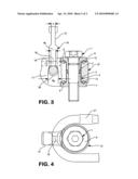
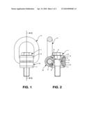
[0007]FIG. 1 shows the front view of a first attachment device,
[0008]FIG. 2 shows a section along line II-II in FIG. 1,
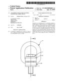
[0009]FIG. 3 shows, partly in section, the side view of a second attachment device, and
[0010]FIG. 4 shows a plan view of the attachment device according to FIG. 3 with the attachment element swung over the fastening element.
[0011]In FIGS. 1 and 2, 1 is a fastening element which is formed by a bolt and on which a bushing 4 comprising two parts 2 and 3 is mounted. The two parts 2 and 3 overlap in the central region of the bushing 4 and are connected to one another by a press fit in the overlapping zone. A spring ring 5 secures the position of the bushing 4 on the fastening element 1.
[0012]At its opposite ends, the bushing 4 has two annular flanges 6 and 7, which merge into the cylindrical part of the bushing 4 via conical surfaces 8 and 9. In the region of the conical surfaces 8 and 9, two series of rolling-contact bodies 12 and 13 are arranged between the bushing 4 and a connecting element 10, which connects the fastening element to an annular attachment element 11, these series of rolling-contact bodies, together with the bushing 4 and the connecting element 10, forming angular roller bearings. The series of rolling-contact bearings 12 and 13 are easy to install in that, first of all, the rolling-contact bodies of the series of rolling-contact bodies 13 are positioned on the conical surface 9, the connecting element 10 is then pushed over the bottom part 3 of the bushing 4, the rolling-contact bodies of the series of rolling-contact bodies 12, thereafter, are lined up in a row on the running surface provided on the connecting element 10, and, following this, the top part 2 and the bottom part 3 of the bushing are pressed together. In a final installation step, the fastening element 1 is forced into the bushing 4 until the spring ring 5 latches into a groove 14 in the interior of the bushing 4.
[0013]In the case of the attachment device according to FIGS. 3 and 4, in which use is made of the same designations for parts which correspond to the parts illustrated in FIGS. 1 and 2, the connecting element 15 is assembled with the fastening element 1 in the same way as has been described above, so that, in this respect, you can refer to what has already been said. The difference between the second embodiment and the first embodiment described above is that the attachment element 16 of the second embodiment is connected in a releasable manner to the connecting element 15. For this purpose, the connecting element 15 is provided with a fork head 17 which has an introduction gap 18 which can be bridged by a transverse bolt 19. The introduction gap 18, which has an inside width W1, is adjoined by an eyelet 20 with an inside width W2, which corresponds at least to 1.5 times the inside width W1 of the introduction gap 18. Using a connecting element 15 with a fork head 17 makes it possible to combine the connecting element 15 with different types of attachment element. It is advantageous here to use attachment elements which, like the attachment element 16 illustrated in FIGS. 3 and 4 and formed by a suspension member, are provided with a flattened zone 21, of which the thickness a is smaller than the inside width W1 of the introduction gap 18.
User Contributions:
comments("1"); ?> comment_form("1"); ?>Inventors list |
Agents list |
Assignees list |
List by place |
Classification tree browser |
Top 100 Inventors |
Top 100 Agents |
Top 100 Assignees |
Usenet FAQ Index |
Documents |
Other FAQs |
User Contributions:
Comment about this patent or add new information about this topic:
Images included with this patent application:
 |  |
 |
| Similar patent applications: | |
| Date | Title |
|---|---|
| 2013-07-18 | Offshore cargo rack for use in transferring loads between a marine vessel and an offshore platform |
| 2013-07-11 | Container-lifting spreader with drive for the telescopic movement of spreader's beams protected against damage by collision |
| 2013-07-25 | Apparatus for aiding installation of carpet |
| 2013-04-11 | Pickup device for animal waste |
| 2013-06-27 | Circumferential cams for mechanical case running tool |
| New patent applications in this class: | |
| Date | Title |
|---|---|
| 2011-07-14 | Combination chopsticks and chopstick rest and apparatus for production of same |
| 2011-06-09 | Handling device and handling method for wafers |
| 2011-05-26 | Chopsticks |
| 2011-05-26 | Device for removing snow from a vehicle |
| 2011-05-12 | Lifting assembly |
| Top Inventors for class "Handling: hand and hoist-line implements" | |
| Rank | Inventor's name |
|---|---|
| 1 | Kenjiro Murakami |
| 2 | Giuseppe Maffeis |
| 3 | Ghee Hua Ng |
| 4 | Nicholas Roy Corson |
| 5 | Giuseppe Maffeis |