Patent application title: Liquid Absorbing Bottle Holder
Inventors:
Katherine Tymczyna (Norwood Park Township, IL, US)
IPC8 Class: AA45F316FI
USPC Class:
2241486
Class name: Removable liquid-holding container held by carrier secured by flaccid member strap-type flaccid member
Publication date: 2010-03-25
Patent application number: 20100072234
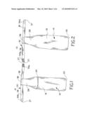
Inventors list |
Agents list |
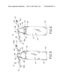
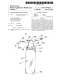
Assignees list |
List by place |
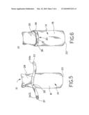
Classification tree browser |
Top 100 Inventors |
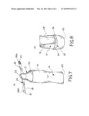
Top 100 Agents |
Top 100 Assignees |
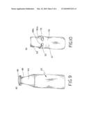
Usenet FAQ Index |
Documents |
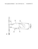
Other FAQs |
Patent application title: Liquid Absorbing Bottle Holder
Inventors:
Katherine Tymczyna
Agents:
LEMPIA BRAIDWOOD LLC
Assignees:
Origin: CHICAGO, IL US
IPC8 Class: AA45F316FI
USPC Class:
2241486
Patent application number: 20100072234
Abstract:
A holder for a liquid containing bottle includes a sleeve section having a
sleeve wall, a closed bottom end, an open top end, and an interior. An
elongate flap extends from a portion of the sleeve section adjacent the
open top end. The flap has a free end and is foldable to a closed
position covering the open top end and overlapping part of the sleeve
section. A releasable fastener mechanism on the flap is configured to
secure the flap in a closed position. The sleeve section can be formed of
an absorbent fabric or a microfiber material. The flap can overlap the
sleeve section to a variable degree when in the closed position altering
a length of the sleeve section to accommodate different length bottles.Claims:
1. A holder for a liquid containing bottle, the holder comprising:a sleeve
section having a sleeve wall, a closed bottom end, an open top end, and
an interior;an elongate flap extending from a portion of the sleeve
section adjacent the open top end, the flap having a free end and being
foldable to a closed position covering the open top end and overlapping
part of the sleeve section; anda releasable fastener mechanism on the
flap configured to secure the flap in the closed position,wherein the
sleeve section is formed of an absorbent fabric.
2. A holder according to claim 1, wherein the absorbent fabric is a microfiber material.
3. A holder according to claim 1, wherein the flap is formed integrally with a portion of the sleeve section and the holder is formed of an absorbent fabric.
4. A holder according to claim 1, wherein the fastener mechanism further comprises a pair of straps extending laterally in opposite directions from the flap near the free end.
5. A holder according to claim 4, wherein each strap carries a part of a securing device capable of securing the flap in the closed position.
6. A holder according to claim 4, wherein the securing device parts are configured to connect to one another and the straps to encircle the sleeve section when secured in a closed position.
7. A holder according to claim 4, wherein the straps each have a securing device that connects directly to the sleeve wall of the sleeve section when secured in the closed position.
8. A holder according to claim 1, wherein the fastener mechanism further comprises an elastic loop sized to be received over the sleeve section.
9. A holder according to claim 1, wherein the sleeve section further comprises a clear window region on a part of the sleeve wall.
10. A holder according to claim 1, wherein the flap can be folded down to overlap less of the sleeve section to cover a taller bottle, and to overlap more of the sleeve section to cover a shorter bottle.
11. A holder for a liquid containing bottle, the holder comprising:a tubular sleeve section having a sleeve wall, a closed bottom end, an open top end, and an interior;a closure flap extending from the sleeve wall adjacent the open top end and having a free end, the flap foldable to a closed position overlapping the sleeve section to cover the open top end; anda fastener mechanism carried near the free end of the flap and configured to fasten the closure flap in the closed position;wherein the flap can overlap the sleeve section to a variable degree when in the closed position altering a length of the sleeve section to accommodate different length bottles.
12. A holder according to claim 11, wherein the flap can be folded to overlap the sleeve section to a lesser degree to cover a taller bottle, and the flap can be folded to overlap the sleeve section to a greater degree to cover a shorter bottle.
13. A holder according to claim 12, wherein both the flap and part of the sleeve section can be folded to overlap the sleeve section to a greater degree to cover a shorter bottle.
14. A holder according to claim 11, wherein the fastener mechanism has a pair of straps affixed near the free end of the flap and extending in opposing directions, wherein, with the flap in the closed position, the pair of straps wrap around a substantial portion of the circumference of the sleeve.
15. A holder according to claim 14, wherein the straps each have hook fasteners that can adhere to the material of the sleeve wall.
16. A holder according to claim 14, wherein the straps each have hook and loop fasteners parts on a distal end, and wherein the fastener part on one strap can adhere to the fastener part on the other strap with the straps wrapped around the circumference of the sleeve and overlapping one another.
17. A holder according to claim 11, wherein the fastener mechanism is a continuous elastic band.
18. A holder according to claim 11, wherein the fastener mechanism includes one or more hook type fastener parts that can connect to the sleeve wall.
19. A holder according to claim 11, wherein the fastener mechanism has a pair of elastic straps extending in opposite directions from the flap near the free end, each strap capable of stretching to accommodate bottles of different diameter or circumference.
20. A holder according to claim 11, wherein the sleeve section further comprises a transparent window region on a part of the sleeve wall.
21. A holder according to claim 11, wherein the sleeve section is formed of a microfiber material.
Description:
RELATED APPLICATION DATA
[0001]This patent is related to and claims priority benefit of U.S. provisional patent application Ser. No. 61/098,307, which was filed on Sep. 19, 2008. The entire disclosure of the above-noted provisional application is hereby incorporated by reference herein.
BACKGROUND
[0002]1. Field of the Disclosure
[0003]The present disclosure is generally directed to bottle holders or sleeves, and more particularly to a leak resistant or liquid absorbing bottle holder.
[0004]2. Description of Related Art
[0005]Some bottles are known to be transported by a user to various locations outside the home for use. Some bottles are also known to contain liquid contents that may leak from the container during use or storage. Some bottles are also known to contain a liquid product that can end up on the outside surfaces of the bottle during and/or after use. Bottles of sunscreen, suntan lotion, suntan oil, body oil, or the like are just some examples. Users often take a bottle of sunscreen or other similar product with them to the beach, to the golf course, to the pool, to the park, to the bike trail, on a hike, and the like. Upon applying the sunscreen, the user will typically continue to touch the bottle, though their hands are covered with the sunscreen liquid. Thus, the bottle often becomes greasy or sticky on its outside surfaces.
[0006]Users may carry a number of items to a location requiring the use of another container or carrier. One type of carrier is a beach bag or a tote bag. However, on a return trip from the beach, other items in the bag may come in contact with the bottle and become contaminated by contact with the greasy or sticky sunscreen bottle. As a result, many users carry their bottles of sunscreen, suntan lotion, suntan oil, body oil, or the like in yet another container to avoid contaminating the other contents of the bag. Users sometimes carry their sunscreen bottle in a separate storage bag such as a sandwich bag, freezer bag, or the like. These types of containers or bags are not particularly attractive. In addition, these types of bags are not configured to accommodate bottles of different size. Further, such bags can themselves become sticky or greasy on both the inside and outside bag surfaces. As a result, the bag can become just as unpleasant to carry as the sticky or greasy bottle would have been. Clear plastic bags are transparent so users can see the contents of the storage bag, but can often become too smeared or messy to see through.
[0007]There are other types of bottles that contain liquids, other than sunscreen bottles, that have similar problems. Hand lotion containers, shampoo bottles, conditioner bottles, and baby bottles are just several of many possible additional examples of such bottles. Any number of these types of different products may be carried when traveling. In one example, a user can take a cold bottle, perhaps containing a cold beverage, from a refrigerator or freezer and place it in a carrier. A cold bottle can develop condensation, which in turn can also make the other contents of a carrier such as a beach bag, tote bag, or brief case wet.
BRIEF DESCRIPTION OF THE DRAWINGS
[0008]Objects, features, and advantages of the present invention will become apparent upon reading the following description in conjunction with the drawing figures, in which:
[0009]FIG. 1 shows a front side of one example of a bottle holder constructed in accordance with the teachings of the present invention and in an empty and flat condition.
[0010]FIG. 2 shows a back side of the bottle holder of FIG. 1.
[0011]FIG. 3 shows the bottle holder of FIG. 1 with a bottle partially inserted into the sleeve section of the holder.
[0012]FIG. 4 shows the bottle holder of FIG. 3 with the bottle completely inserted into the sleeve section.
[0013]FIG. 5 shows the bottle holder of FIG. 4 with the closure flap partly closed.
[0014]FIG. 6 shows a back side of the bottle holder of FIG. 5 and with the closure flap completely closed and fastened.
[0015]FIG. 7 shows the bottle holder of FIG. 1 with a smaller sized bottle partially inserted into the sleeve section of the holder.
[0016]FIG. 8 shows the bottle holder of FIG. 7 with the bottle completely inserted in the sleeve section and with the closure flap completely closed and fastened.
[0017]FIG. 9 shows a front side of another example of a bottle holder with a different fastener mechanism.
[0018]FIG. 10 shows a back side of another example of a bottle holder with another different fastener mechanism.
[0019]FIG. 11 shows a back side of another example of a bottle holder with a transparent window region in the sleeve section.
DETAILED DESCRIPTION OF THE DISCLOSURE
[0020]The bottle holders disclosed and described herein solve or improve upon one or more of the above noted and/or other problems and disadvantages with known bottles and with bottle storage and holding devices and methods. The disclosed bottle holders can be formed from a fabric material that either does not leak or that absorbs liquid coming into contact with the fabric. The disclosed bottle holders can also be configured to accommodate bottles of different shape, height, diameter, and the like. The disclosed bottle holders can also include an adjustable flap and fastener mechanism that can accommodate bottles of various sizes and yet close and secure the bottle holder over a bottle stored in the holder.
[0021]Turning now to the drawings, FIG. 1 shows one example of a bottle holder 10 constructed in accordance with the teachings of the present invention. As shown in FIG. 1, the holder 10 can include a cylindrical or tubular shaped sleeve section 14. As shown in FIGS. 1 and 2, the holder 10 generally has a front side 16 and a back side 18. The front side 16 and the back side 18 on the sleeve section 14 form a sleeve wall that can be joined at the sides via sewn seams or the section can be formed as a contiguous tube like a sock or a shirt sleeve. The front side 16 and the back side 18 can also be joined at a bottom closed end 20, which closes off an interior 24 of the sleeve section 14. The closed end 20 and the interior 24 thus form a closed pocket to receive a bottle. The sleeve section 14 of the holder 10 has an open top end 22 that is open to permit a bottle to be inserted into or removed from the interior 24.
[0022]The disclosed holder 10 also has a closure that can close the holder and be secured in a closed position. As shown in FIG. 1, the front side 16 of the holder 10 is shorter in length than the back side 18. In the disclosed example, the closure has an elongate closure flap 28 that is formed extending from the lengthier back side 18 at the top edge 26 of the sleeve section 14. In the disclosed example, the flap 28 is formed integrally with and as an extension of the back side 18 material. In an alternate example, the flap 28 can be attached to the sleeve section 14 as a separate piece.
[0023]In the disclosed example, the closure also employs a closure device or fastener mechanism 30, at least a portion of which can be carried on the closure flap 28. The closure flap 28 can employ various types of fastener mechanisms to secure the flap in a closed position. In one example as shown in FIGS. 1-6, the fastener mechanism 30 has a pair of elongate straps 36 extending in opposite directions from the side edges of the flap 28 near a free end 38 of the flap. The pair of straps 36 can be either affixed to or integrally formed as part of the flap 28. In the example shown in FIG. 6, the free ends 37 of the individual straps 36 can employ a securing device configured to adhere or otherwise connect to one another after being wrapped around the sleeve section 14 of the holder 10. Each strap 36 in this example carries a securing device or fastener part 34a, 34b such as a hook and loop-type fastener material patch like VELCRO®, a snap part, or the like. In an alternate example, the individual straps 36 can each be the securing device and be provided as an elongate, complimentary, hook and loop fastener strip that allows for lengthwise adjustability, i.e., a variable degree of strap overlap between the straps 36 while being capable of attaching to one another to accommodate different shape and diameter bottles. Alternatively, the straps 36, including securing devices, such as snaps or the hook-and-loop fastener patches 34a, 34b, carried on the free ends 37 can be made of elastic or stretchable, resilient material to adjust to various bottle sizes. In such an example, the straps 36 can employ smaller, localized, complimentary fastener parts or securing devices, such as snaps, clasps, hook and loop patches, side release buckles, or the like, and the straps can be elastic in order to accommodate different sized bottles and yet connect the fastener parts securely. In another example, the straps can be ties.
[0024]The holder 10 in the disclosed example can also accommodate different height bottles as illustrated by FIGS. 3-8. A bottle 12 with a top cap 32 can be inserted into the open top 22 of the sleeve section 14 as shown in FIG. 3. The bottle 12 can be fully inserted into the sleeve section, bottoming out against the closed end 20, as shown in FIG. 4, when not in use. The closure flap 28 can be of a sufficient length to overlap the sleeve section 14 to a variable degree when closed. Also, the fastener mechanism 30 can fasten at virtually any position along the length of the sleeve section 14 with a bottle inserted therein. These features alter a length of the sleeve section 14 to accommodate different length bottles. The closure flap 28 can be folded over the top cap 32 of the bottle 12, as shown in FIG. 5. The fastener mechanism 30 can then be fastened around the bottle 12 and the sleeve section 14.
[0025]The holder 10 can accommodate taller bottles by the flap 28 being folded over the open top end 22 and the bottle cap 32. The taller bottle places fastener mechanism 30 nearer the open top end, as in FIGS. 5 and 6. The flap 28 can be folded down to a lesser length to overlap less of the sleeve section and cover the taller bottle as shown in FIG. 6. The holder 10 can accommodate shorter bottles by the flap 28, and even part of the sleeve section 14, being folded over the bottle cap 32, as in FIGS. 7 and 8. The fastener mechanism 30 can fasten at a position closer to the closed bottom end 20 of the sleeve section 14, as in FIG. 8, for shorter bottles. The closure flap 28 can fold to a greater length to overlap more of the sleeve section and cover the shorter height bottle.
[0026]FIG. 3 shows the bottle holder 10 in an in-use condition with a bottle 12 partially inserted into the interior 24 of the holder 10, but with the bottle cap 32, i.e., its dispensing end, exposed through the open top end 22. The contents of the bottle can be dispensed in the configuration of FIG. 3. As shown in FIG. 4, the bottle 12 can be completely inserted all the way down to the closed end 20 of the sleeve section 14 when stored in the holder 10. For use, the fastener mechanism 30 can be released and the closure flap 28 opened. The bottle 12 can be pushed or snaked back up toward the open top end 22 of the sleeve section 14 to expose a top cap 32 on the bottle to allow access for use as represented in FIG. 3. Thus, the bottle 12 need not be removed from the holder 10 until the contents are depleted or the holder is to be cleaned.
[0027]As shown in FIGS. 5 and 6, when the flap 28 is folded down over the open top end 22 to close off the sleeve section 14, the closure straps 36 can then be wrapped around the bottle 12 and sleeve section 14 in opposite directions. The free ends 37 can then be secured to one another as shown in FIG. 6. Once the fastener mechanism 30 is secured, the bottle 12 is retained within the sleeve section 14 and is completely covered by the holder 10 as shown in FIG. 6.
[0028]In another example as shown in FIG. 9, a holder 40 can include a sleeve section 42 with an open top end and an elongate closure flap 44. A fastener mechanism 46 is carried on the closure flap 44 near its free end 48. The fastener mechanism 46 in this example is a continuous elastic or resilient loop or band. With a bottle inserted into the sleeve section 42, the closure flap 44 can be folded over. The elastic loop 46 can be slipped over the circumference of the holder 40 and bottle to retain the closure flap 44 in the closed position. The elastic band can secure to the holder at any position along the sleeve section 42.
[0029]In another example as shown in FIG. 10, a holder 50 can include a sleeve section 52 with an open top end and an elongate closure flap 54. A fastener mechanism is again carried on the closure flap 54 near its free end. A fastener mechanism in this example has a pair of straps 53, each with a fastener part 56a, 56b on the respective free ends of the straps. In this example, the fastener parts 56a, 56b can each be a hook-type or other suitable material that can adhere directly to the exterior surface of the sleeve section 52 of the holder 50. In this example, the sleeve section 52 can define part of the fastener mechanism and be formed of a material that includes a fabric texture, i.e., a loop pile. The texture can be configured to adhere to the hook element of a hook and loop-type fastener. Thus, the fastener parts 56a, 56b can each be such a hook element and the sleeve section 52 can provide the loop element so that the ends of each of the straps 53 can be applied and adhere directly to any portion of the exterior surface on the sleeve wall 57 as illustrated in FIG. 10.
[0030]In another example, a strip or patch of loop element can be provided along a length of the sleeve section 52 as part of the fastener mechanism. The straps can wrap around the holder and bottle and adhere to the strip. In another example, the flap can employ a fastener part directly on the flap near the free end. The flap can adhere either directly to the sleeve wall material, as in the example of FIG. 10, or can adhere to a loop material strip on the sleeve section. As with all of the examples described herein, the locations of the hook and loop materials or other fastener part types can be changed and the components reversed on the flap and the sleeve and yet function as intended.
[0031]In yet another alternate example shown in FIG. 11, a holder 60 can include a sleeve section 62 with an elongate closure flap 64. A wall 65 of the sleeve section 62 has a front side and a back side 66. The back side 66 of the sleeve wall 65 can include a clear or transparent window 68. As shown in FIG. 11, the transparent window 68 can allow a user to see and identify the contents of the holder 60. The bottle's label can be positioned so as to be visible through the window 68. Thus, the user need not open the holder 60 and remove the bottle to identify the contents.
[0032]In the disclosed examples, once the fastener mechanisms are secured, a bottle can be transported without contaminating adjacent objects and without the user's hands becoming greasy, sticky, or dirty simply from carrying or touching the bottle. The bottle can stay in the holder during use. If the bottle leaks, the fabric holder will absorb or contain the leaked liquid. If the user's hands become covered in the liquid, the sleeve can absorb some of the liquid from their hands when the user touches the holder. In the disclosed example, the bottle holders can be formed of a fabric material that is flexible. In one example, the fabric material can also have a degree of elasticity or stretchiness, if desired. In one particular example, the fabric material can be a microfiber material or a synthetic blend material that is liquid absorbent. In such an instance, any liquid escaping from the bottle and/or coating the outside surface of the bottle and/or contacting the exterior of the holder may be absorbed by the fabric material.
[0033]The disclosed bottle holders can be formed of fabric materials with textile patterns, a variety of colors, and other configurations in order to create a variety of different looks. The holders can be formed to provide an aesthetically pleasing decorative cover for bottles. Thus, the bottle itself need not be visible when stored in the holder. The fabric material can be die cut, formed to shape, and sewn. However, other manual and/or automated manufacturing processes can be utilized to create the disclosed holders as well.
[0034]The bottle holders can be cut or formed from one piece of fabric material that is folded and sewn or otherwise joined with one side seam and a bottom seam. Alternatively, the bottle holder can be cut and sewn from two pieces of fabric, one being a shorter front portion of the sleeve section and another being a longer back portion of the sleeve with the elongate closure flap integral to the back portion. The two pieces can joined along two side seams and along the closed bottom end of the sleeve section. However, the specific methods of manufacture can vary and still remain within the teachings of the present invention.
[0035]As will be evident to those having ordinary skill in the art upon reading this disclosure, the specific configuration and construction of the disclosed holders, parts, and features can vary from the examples shown and described herein. In addition, the materials used to form the various components of the holder can also vary and need not be fabric. Non-fabric or other synthetic materials may become known or available, or may be developed, that are suitable for use in creating a bottle holder with the features and functionality as described herein.
[0036]As shown in FIGS. 1 and 2, the disclosed fabric material holders are relatively flat when empty and can be very light weight when no bottle is stored in the sleeve section's interior. Thus, the holders can be folded or rolled up and stored easily while taking up very little storage space. In addition, the holders disclosed and described herein may be machine washed in the regular laundry or may be hand washed, dry cleaned, or otherwise decontaminated as needed, while observing caution due to any material limitations, characteristics, and/or concerns.
[0037]Although certain bottle holders and features have been described herein in accordance with the teachings of the present disclosure, the scope of coverage of this patent is not limited thereto. On the contrary, this patent covers all embodiments of the teachings of the disclosure that fairly fall within the scope of permissible equivalents.
User Contributions:
comments("1"); ?> comment_form("1"); ?>Inventors list |
Agents list |
Assignees list |
List by place |
Classification tree browser |
Top 100 Inventors |
Top 100 Agents |
Top 100 Assignees |
Usenet FAQ Index |
Documents |
Other FAQs |
User Contributions:
Comment about this patent or add new information about this topic:
Images included with this patent application:
 |  |
 |  |
 |  |
 |
| Similar patent applications: | |
| Date | Title |
|---|---|
| 2010-09-30 | Adjustable position bottle holster |
| 2011-03-03 | Elastic casing article holder |
| 2011-02-24 | Combination body cooler and bottle holder |
| 2012-01-05 | Waistpack having quick access/deposit hydration bottle |
| 2010-10-28 | Flexible bag including bottle carrier sections |
| New patent applications in this class: | |
| Date | Title |
|---|---|
| 2015-10-29 | Body harness device |
| 2015-03-12 | Wearable beverage container holder |
| 2014-11-20 | Drinking bottle strap |
| 2014-10-23 | Water bottle strap carrier |
| 2014-09-18 | Carrying device |
| Top Inventors for class "Package and article carriers" | |
| Rank | Inventor's name |
|---|---|
| 1 | Chris Sautter |
| 2 | Zac Elder |
| 3 | Peter Douglas Hubbard |
| 4 | Douglas Harland Murdoch |
| 5 | Jeffrey M. Aftanas |