Patent application title: DRILL BIT SHAFT STRUCTURE FOR EXCAVATION APPARATUS
Inventors:
Yoshihide Kiyosawa (Azumino-Shi, JP)
Yoshihide Kiyosawa (Azumino-Shi, JP)
Assignees:
Harmonic Drive Systems Inc.
IPC8 Class: AE21B1720FI
USPC Class:
175 73
Class name: Boring or penetrating the earth means traveling with tool to constrain tool to bore along curved path
Publication date: 2010-03-18
Patent application number: 20100065333
Inventors list |
Agents list |
Assignees list |
List by place |
Classification tree browser |
Top 100 Inventors |
Top 100 Agents |
Top 100 Assignees |
Usenet FAQ Index |
Documents |
Other FAQs |
Patent application title: DRILL BIT SHAFT STRUCTURE FOR EXCAVATION APPARATUS
Inventors:
Yoshihide KIYOSAWA
Agents:
BUCHANAN, INGERSOLL & ROONEY PC
Assignees:
Harmonic Drive Systems Inc.
Origin: ALEXANDRIA, VA US
IPC8 Class: AE21B1720FI
USPC Class:
175 73
Patent application number: 20100065333
Abstract:
The drill bit shaft structure for an excavation apparatus has a
thin-walled shaft portion formed on a hollow drill bit shaft. The
thin-walled shaft portion has a thinner wall than that of shaft portions
of the hollow drill bit shaft adjacent to both ends of the thin-walled
shaft portion. A cylindrical body provided with an adjustable joining
structure is disposed so as to envelop the thin-walled shaft portion.
Both ends of the cylindrical body are connected to the shaft portions of
the hollow drill bit shaft adjacent to the both ends of the thin-walled
shaft portion. The direction of excavation is controlled by bending the
thin-walled shaft portion and the cylindrical body.Claims:
1. A drill bit shaft structure for an excavation apparatus, comprising:a
hollow drill bit shaft;a thin-walled shaft portion formed on the hollow
drill bit shaft, which has a predetermined length along an axial
direction of the hollow drill bit shaft, and which has a thinner wall
than that of shaft portions of the hollow drill bit shaft adjacent to
both ends of the thin-walled shaft portion; anda cylindrical body
provided with an adjustable joining structure and disposed so as to
envelop the thin-walled shaft portion; whereinthe cylindrical body has
two end parts connected to the shaft portions of the hollow drill bit
shaft adjacent to the both ends of the thin-walled shaft portion; andthe
direction of excavation is controlled by bending the thin-walled shaft
portion and the cylindrical body.
2. The drill bit shaft structure for an excavation apparatus according to claim 1, wherein the adjustable joining structure of the cylindrical body is an Oldham coupler.
3. The drill bit shaft structure for an excavation apparatus according to claim 1, wherein the adjustable joining structure of the cylindrical body is formed by wrapping metal wire of a predetermined thickness in multiple layers in a coil shape.
4. The drill bit shaft structure for an excavation apparatus according to claim 1, wherein:an inside diameter of the thin-walled shaft portion is equal to that of the remaining shaft portion of the hollow drill bit shaft, andan outside diameter of the thin-walled shaft portion is less than that of the remaining shaft portion of the hollow drill bit shaft.
5. The drill bit shaft structure for an excavation apparatus according to claim 4, wherein a shock absorber comprising heat-resistant rubber or other resin material is disposed between the thin-walled shaft portion and the cylindrical body.
Description:
BACKGROUND OF THE INVENTION
[0001]1. Field of the Invention
[0002]The present invention relates to an excavation apparatus used for the excavation of oil wells, gas wells, and the like, and more particularly to a drill bit structure that can easily bend in order to change the direction of excavation.
[0003]2. Description of the Related Art
[0004]An easily bendable drill bit shaft is necessary for an excavation apparatus in which the drill bit shaft (drill pipe) bends to change the direction of excavation. However, the drill bit shaft must transmit excavation torque to the drill bit at the distal end, bear a predetermined axial load, and allow excavation liquid (muddy water) to pass through the hollow space thereof. A thick-walled shaft having high bending rigidity is therefore used by necessity as the drill bit shaft. Significant bending stress is produced when a highly rigid drill bit shaft is bent. Therefore, a drill bit shaft cannot be bent to a significant degree in order to prevent the rotating bending fatigue limit from being exceeded.
[0005]It is proposed in JP-A 09-217576 to provide a joint part such as a universal joint to the connecting portion of a drill bit. In JP-A 08-270369, a drill bit shaft is connected via a flexible joint having a predetermined length, and bending-induced excessive stress is prevented from acting on the drill bit shaft.
SUMMARY OF THE INVENTION
[0006]An object of the present invention is to provide a drill bit shaft structure for an excavation apparatus in which the drill bit shaft can be bent without producing high bending stress.
[0007]The drill bit shaft structure for an excavation apparatus according to the present invention, comprises:
[0008]a hollow drill bit shaft;
[0009]a thin-walled shaft portion formed on the hollow drill bit shaft, which has a predetermined length along an axial direction of the hollow drill bit shaft, and which has a thinner wall than that of shaft portions of the hollow drill bit shaft adjacent to both ends of the thin-walled shaft portion; and
[0010]a cylindrical body provided with an adjustable joining structure and disposed so as to envelop the thin-walled shaft portion; wherein
[0011]the cylindrical body has two end parts connected to the shaft portions of the hollow drill bit shaft adjacent to the both ends of the thin-walled shaft portion; and
[0012]the direction of excavation is controlled by bending the thin-walled shaft portion and the cylindrical body.
[0013]An Oldham coupling structure can be used as the adjustable joining structure of the cylindrical body. Alternately, a joint formed by wrapping metal wire of a predetermined thickness in multiple layers in a coil shape may also be used.
[0014]It is preferable for the inside diameter of the thin-walled shaft portion to be equal to that of the shaft portions on both sides, and for the outside diameter of the thin-walled shaft portion to be less than that of the shaft portions on both sides. This allows the diameter of the hollow part of the drill bit shaft to remain constant, and fluid to flow smoothly through the hollow part. A gap is formed between the external peripheral surface of the thin-walled shaft and the internal peripheral surface of the cylindrical body that surrounds the shaft. Therefore, the thin-walled shaft and the cylindrical body can be prevented from coming into contact with each other while in a flexed state.
[0015]A shock-absorbing material comprising heat-resistant rubber or other resin material may be disposed between the thin-walled shaft and the cylindrical body in order to reliably prevent contact between the thin-walled shaft and the cylindrical body.
[0016]In the drill bit shaft structure for an excavation apparatus according to the present invention, a thin-walled shaft having a predetermined length is formed in part of the drill bit shaft, making it easier to bend the drill bit shaft. In addition, a reduction in the transmission of excavation torque or the like due to the formation of the thin-walled shaft can be compensated for with a cylindrically configured adjustable joining structure disposed so as to envelop the thin-walled shaft.
[0017]It is therefore possible to use a thick-walled, sufficiently rigid drill bit shaft for the entire structure, and the thin-walled shaft enveloped in the cylindrical body can easily bend without producing excessive stress. The transmission of excavation torque and the like can be maintained by the cylindrically configured adjustable joining structure.
BRIEF DESCRIPTION OF THE DRAWINGS
[0018]FIG. 1 is a schematic partial structural view of the excavation apparatus used in the present invention;
[0019]FIG. 2 is an explanatory drawing showing the flexible shaft portion of the drill bit shaft;
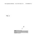
[0020]FIG. 3 is an explanatory drawing showing another example of the cylindrical body; and
[0021]FIG. 4 is an explanatory drawing showing the flexible shaft portion provided with a shock-absorbing material.
DESCRIPTION OF THE PREFERRED EMBODIMENTS
[0022]Embodiments of the drill bit shaft structure for an excavation apparatus in which the present invention was used will now be described with reference to drawings.
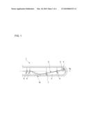
[0023]FIG. 1 is an explanatory drawing showing the entire structure of the excavation apparatus. The excavation apparatus 1 has a drill string connected to a drill bit shaft 2, a drill collar 3 is connected coaxially to the distal end of the drill bit shaft 2, and a drill bit 4 is supported on the distal end of the drill collar 3. A rotation drive apparatus (not shown) for rotating the drill string is disposed toward the back end of the drill string.
[0024]The drill bit shaft 2 that constitutes part of the drill string is rotatably supported so as to be coaxial to an excavation hole 5 by a plurality of support bearing mechanisms 6 disposed at predetermined intervals along the excavation hole 5. At a position along the drill bit shaft 2, the drill bit shaft 2 is supported in a rotatable state by an eccentric support bearing mechanism 7 that is in an offset position from the support positions provided by the other support bearing mechanisms 6.
[0025]The area of the drill bit shaft 2 supported by the eccentric support bearing mechanism 7 is in an offset position from the areas supported on the two sides thereof. Therefore, the drill bit shaft 2 is bent as an entire structure, and the shaft portion that protrudes toward the distal end from the support bearing mechanisms 6 is extended in a slightly inclined direction relative to a central axis 5a of the excavation hole 5. Accordingly, the excavation direction of the drill bit 4 that is attached toward the distal end of the drill bit shaft 2 is inclined in relation to the central axis 5a.
[0026]As an entire structure, the drill bit shaft 2 is a hollow shaft having a constant wall thickness, and a flexible shaft portion 10 that is easily bent compared to other portions is formed in a part thereof. The flexible shaft portion 10 of the drill bit shaft 2 is bent to a significant degree by the eccentric support bearing mechanism 7.
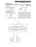
[0027]FIG. 2 is a schematic partial cross-sectional view showing the flexible shaft portion 10 of the drill bit shaft 2. Within the flexible shaft portion 10, part of the hollow drill bit shaft 2 is made into a thin-walled shaft portion 21 having thinner walls than shaft portions 22, 23 on both sides over a predetermined length, and a cylindrical body 30 provided with an adjustable joining structure is coaxially disposed so as to envelop the thin-walled shaft portion 21.
[0028]The wall thickness of two end parts 21a, 21b of the thin-walled shaft portion 21 gradually increases and ultimately becomes contiguous with adjacent portions 22a, 23a of the shaft portions 22, 23 on both sides. Also, the inside diameter of the thin-walled shaft 21 is equal to the inside diameter of the shaft portions 22, 23 on both sides, and a hollow part 2a having a constant inside diameter extends through the drill bit shaft 2. Therefore, the outside diameter of the thin-walled shaft portion 21 is less than that of the shaft portions 22, 23 on both sides, and has a proportionately thinner wall.
[0029]The cylindrical body 30 is longer than the thin-walled shaft portion 21, and the two end parts thereof are contiguously fixed to the adjacent portions 22a, 23a of the shaft portions 22, 23 on the two sides of the thin-walled shaft portion 21. The inside diameter and outside diameter of the cylindrical body 30 are constant, respectively, and a ring-shaped gap 24 is formed between the internal peripheral surface 31 of the cylindrical body and the external peripheral surface 21c of the thin-walled shaft portion 21.
[0030]The cylindrical body 30 is provided with an adjustable joining structure. In the present example, an Oldham coupling structure is provided, and a plurality of Oldham rings having the same diameter are connected in a coaxial state. More specifically, the two end parts of the cylindrical body 30 are defined by wide Oldham rings 32, 33, and Oldham rings 34, 35 are alternately connected in a coaxial state therebetween. Oldham rings 34 are provided with a pair of key grooves 34a, 34a formed at point-symmetrical positions on the circular end face on one side thereof, and a pair of key grooves 34b, 34b formed at point-symmetrical positions on the circular end face on the other side. The key grooves 34a, 34a and the key grooves 34b, 34b are formed in positions offset at 90 degrees. The other Oldham rings 35 are provided with a pair of keys 35a, 35a formed at point-symmetrical positions on the circular end face on one side thereof, and a pair of keys 35b, 35b that are formed at point-symmetrical positions on the circular end face on the other side. The keys 35a, 35a and the keys 35b, 35b are formed in positions offset at 90 degrees. The Oldham rings 34, 35 are connected so as to be able to move a short distance in a radial direction relative to each other.
[0031]In this arrangement, the direction of rotation of the drill bit shaft 2 is constant. Therefore, to prevent backlash in the direction of rotation in the Oldham coupling structure, the Oldham rings can be shifted in advance in the direction of relative rotation and connected without any gaps so that no backlash occurs in the direction of rotation of the drill bit shaft 2.
[0032]The flexible shaft portion 10 composed of the thin-walled shaft portion 21 and the cylindrical body 30 can bend easier than the other shaft portions 22, 23 in the drill bit shaft 2 provided with the flexible shaft portion 10 constituted in this manner. Therefore, high bending stress can be prevented from acting on the drill bit shaft 2. The excavation torque of the thin-walled shaft portion 21 is transmitted less efficiently than that of the other shaft portions 22, 23, but the reduction in the transmission of excavation torque or the like is compensated for by the cylindrical body 30, and the same stress transmission characteristics as those of the other shaft portions 22, 23 can be maintained.
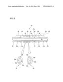
[0033]FIG. 3 is an explanatory view showing another example of the cylindrical body. The cylindrical body 40 shown in this drawing is formed into a cylinder by wrapping metal wire of a predetermined thickness in multiple layers in a coil shape.
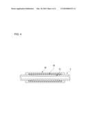
[0034]In this configuration, a cylindrical shock absorber composed of heat-resistant rubber or other resin material may be disposed between the thin-walled shaft portion 21 and the cylindrical body 30, as shown in FIG. 4. In this manner, contact between the thin-walled shaft portion 21 and the cylindrical body 30 can be prevented.
User Contributions:
comments("1"); ?> comment_form("1"); ?>Inventors list |
Agents list |
Assignees list |
List by place |
Classification tree browser |
Top 100 Inventors |
Top 100 Agents |
Top 100 Assignees |
Usenet FAQ Index |
Documents |
Other FAQs |
User Contributions:
Comment about this patent or add new information about this topic:
Images included with this patent application:
 |  |
 |  |
 |
| Similar patent applications: | |
| Date | Title |
|---|---|
| 2013-01-24 | Drill bits with sensors for formation evaluation |
| 2010-09-16 | Drill head for a tunneling apparatus |
| 2012-02-02 | Control system for mud cleaning apparatus |
| 2009-05-07 | Method and system for controlling an excavating apparatus |
| 2011-07-14 | Drill bit bearing contact pressure reduction |
| New patent applications in this class: | |
| Date | Title |
|---|---|
| 2016-03-10 | Apparatus with a rotary seal assembly axially coincident with a shaft tilting focal point |
| 2015-12-31 | Vertical-screw-auger conveyer feeder |
| 2015-05-14 | Hydroplaning reducing slip ring apparatus |
| 2015-03-19 | System and method for horizontal directional drilling and product pulling through a pilot bore |
| 2015-02-05 | Adjustable bent housing for directional drill string |
| New patent applications from these inventors: | |
| Date | Title |
|---|---|
| 2021-12-30 | Strain wave gearing unit |
| 2016-02-18 | Wave generator of strain wave gearing |
| 2016-01-28 | Wave generator of strain wave gearing |
| 2015-10-22 | Hollow-type strain wave gearing unit |
| 2015-10-08 | Strain wave gearing unit |
| Top Inventors for class "Boring or penetrating the earth" | |
| Rank | Inventor's name |
|---|---|
| 1 | David R. Hall |
| 2 | Anthony A. Digiovanni |
| 3 | Danny E. Scott |
| 4 | Youhe Zhang |
| 5 | Steven R. Radford |