Patent application title: LIQUID TREATMENT MODULE
Inventors:
Xiaowei Sun (Jiangsu Province, CN)
Xiaoming Sun (Jiangsu Province, CN)
Huanqing Shao (Jiangsu Province, CN)
Borong Zhan (Jiangsu Province, CN)
IPC8 Class: AB03C502FI
USPC Class:
204665
Class name: Apparatus apparatus for electrical (including simultaneous electrical and magnetic) separation or purification of liquid or magnetic treatment of liquid (other than separation) with filter (e.g., electrostatic filter, etc.)
Publication date: 2010-03-11
Patent application number: 20100059382
Inventors list |
Agents list |
Assignees list |
List by place |
Classification tree browser |
Top 100 Inventors |
Top 100 Agents |
Top 100 Assignees |
Usenet FAQ Index |
Documents |
Other FAQs |
Patent application title: LIQUID TREATMENT MODULE
Inventors:
Xiaowei Sun
Xiaoming Sun
Huanqing Shao
Borong Zhan
Agents:
WARE FRESSOLA VAN DER SLUYS & ADOLPHSON, LLP
Assignees:
Origin: MONROE, CT US
IPC8 Class: AB03C502FI
USPC Class:
204665
Patent application number: 20100059382
Abstract:
The present invention relates to a liquid treatment module, which
comprises power distribution panels, electrode plates and a framework
with side plates. The two power distribution panels are fixed on the two
side plates. The power distribution panels have electrode plates located
on inner side of the panels. There are two or more double-sided electrode
plates placed in stacks between the two distribution panels which are
connected to the DC power supply through the electric wires. There are
separators placed between the adjacent electrode plates to provide the
flow channels. Each flow channel is connected with the inlet and outlet
holes on the side plates. The exposed surface of the power distribution
panels, double-sided electrode plates and the separators are bonded and
sealed by the insulating package. This invention has characteristics of
simple structure, large liquid handling capacity, high efficiency, and
can be used to process liquids of various kinds including water, wine,
fruit juices, beverages, dairy products and chemical wastes from various
sources for impurities removal.Claims:
1. A liquid treatment module, comprising power distribution panels (2),
electrode plates, and a framework (5) with two side plates (1), wherein
the liquid treatment module has the following characteristics:a) the two
power distribution panels (2) are fixed on the side plates (1) by
connectors (3);b) electrode plates (24) are connected to the inside part
of the power distribution panels (2);c) two or more double-sided
electrode plates (4) are stacked between the two power distribution
panels (2);d) the power distribution panels (2) are connectable to a DC
power supply by electrical wires;e) a separator (10) is placed between
the neighboring double-sided electrode plates (4) to provide liquid
channels for liquid to pass through;f) each liquid channel is connected
to two inlet and outlet holes on the side plates (1); andg) exposed
surfaces of the power distribution panels (2), the double-sided electrode
plates (4) and the separator (10) are bonded to a package (9) to provide
support, seal and insulation.
2. The liquid treatment module of claim 1, wherein the power distribution panels (2) are metallic conductive panels.
3. The liquid treatment module of claim 1, wherein each of the power distribution panels (2) is comprised of an insulation plate (21), a conductor (22) and a collector plate (23), attached in sequence on one side of the insulation plate (21).
4. The liquid treatment module of claim 3, wherein there is a transition layer (26) on the surface of the insulation plate (21), and the conductor (22) is composed of a connection part (22-1) which extends from a transition layer (26), a securing part (22-2) that anchored to the transition layer (26), and an electrical power distribution part (22-3) on the surface of the transition layer (26).
5. The liquid treatment module of claim 3, wherein a double-sided electrode plate (4) is comprised of a conductor plate (41) and two electrode plates (42) attached to the two sides of the conductor plate (41).
6. The liquid treatment module of claim 1, wherein there is an intermediate power distribution panel (6) placed between the double-sided electrode plates (4) with electrode plates (64) on both sides of the intermediate power distribution panel.
7. The liquid treatment module of claim 6, wherein the intermediate power distribution panel (6) is made of metallic conductive plates.
8. The liquid treatment module of claim 6, wherein the intermediate power distribution panel (6) is comprised of an insulation plate (61), and conductors (62) and collector plates (63) which are sequentially connected to both sides of the insulation plate (61).
9. The liquid treatment module of claim 8, wherein there is a transition layer (66) on the surface of the insulation plate (61), and the conductor (62) is composed of a connection part (62-1) which extends from the transition layer (66), a securing part (62-2) that anchored to the transition layer (66), and an electrical power distribution part (62-3) on the surface of the transition layer (66).
10. The liquid treatment module of claim 3, wherein a graphite foil is utilized for the collector plates of the power distribution panels (2), the conductor plates (41) of the double-sided electrode plates (4), and the collector plates (63) of the intermediate power distribution panels (6).
11. The liquid treatment module of claim 1, wherein the separator (10) comprises at least one layer of nets, grooved plates, or soft sheets or boards with openings or holes.
12. The liquid treatment module of claim 11, wherein the separator is a bag made of the net with four sides sealed and contains a double-sided electrode plate in the bag.
13. The liquid treatment module of claim 1, wherein the liquid flow channel contains fillers which can allow ions to pass through.
14. The liquid treatment module of claim 1, further comprising two liquid distributing pipes (8), wherein said two liquid distribution pipes (8) penetrate through the two liquid inlet and outlet holes located on the two side plates (1), and are fastened to the two side plates (1) by flanges (7).
15. The liquid treatment module of claim 1, further comprising two liquid distributing pipes (8), wherein said two liquid distribution pipes (8) penetrate through the two liquid inlet and outlet holes located on the two side plates (1), the pipe guiding holes (25) on the power distribution panels (2), the pipe guiding holes (43) on the double-sided electrode plates (4), and are fastened to the side plates (1) by flanges (7).
16. The liquid treatment module of claim 14, wherein:the liquid distributing pipe (8) includes an outer pipe (82) and an inner pipe (83) located inside the outer pipe (82) with the same axis;both the outer pipe (82) and the inner pipe have slits along the axis for liquid to flow in an out;the two outer pipes (82) have liquid flow slits in the opposite directions, one up and one down;the inner pipe (83) has the slit in opposite direction with its corresponding outer pipe (82); andone end of the outer pipe (82) and inner pipe (83) are tightly connected by using the sealing heads (81), another end of the outer pipe (82) and inner pipe (83) are connected and sealed by the cover (84).
17. The liquid treatment module of claim 15, wherein:the liquid distributing pipe (8) includes an outer pipe (82) and an inner pipe (83) located inside the outer pipe (82) with the same axis;both the outer pipe (82) and the inner pipe have slits along the axis for liquid to flow in an out;the two outer pipes (82) have liquid flow slits in the opposite directions, one up and one down;the inner pipe (83) has the slit in opposite direction with its corresponding outer pipe (82); andone end of the outer pipe (82) and inner pipe (83) are tightly connected by using the sealing heads (81), another end of the outer pipe (82) and inner pipe (83) are connected and sealed by the cover (84).
18. The liquid treatment module of claim 5, wherein a graphite foil is utilized for the collector plates of the power distribution panels (2), the conductor plates (41) of the double-sided electrode plates (4), and the collector plates (63) of the intermediate power distribution panels (6).
19. The liquid treatment module of claim 9, wherein a graphite foil is utilized for the collector plates of the power distribution panels (2), the conductor plates (41) of the double-sided electrode plates (4), and the collector plates (63) of the intermediate power distribution panels (6).
Description:
TECHNICAL FIELD
[0001]This invention relates to modules of a liquid treatment device for impurity removal.
TECHNICAL BACKGROUND
[0002]There are many methods for liquid treatments to remove impurities, especially for water treatment. Typical treatment methods include distillation, reverse osmosis, electrodialysis, ion exchange, and freezing. Among them, the major methods utilized for large industrial scale applications include:
[0003](1) Ion exchange: It uses ion exchange resins to treat liquid. The price of ion exchange resins is very high, and the process needs strong acids and alkali for resin regeneration, which produces secondary pollution. Moreover, the maintenance of the equipment is complicated.
[0004](2) Reverse osmosis: This is the most commonly used industrial water purification method. It has advantages such as high desalination rate, simple process, etc. However, the macromolecule membranes are easily polluted and fouled by the organic substances, calcium and chlorine in water. It requires very restrictive pre-treatment system and the addition of several types of antioxidant and anti-scale inhibitor. These increase the complexity of the treatment system, and may cause troubles in system operation and maintenance.
[0005](3) Electrodialysis: It is composed of the electrode plates, separation membrane, and ion exchange resins. Under the attraction forces of a DC electrical field, ions move through the membranes and are adsorbed on the ion exchange resins. However, the incorporated membranes are easily fouled, like in the reverse osmosis. Also, such treatment can only get rid of ions, and it has no effects on organic substances, colloid particles or other particles, or suspended solids. Moreover, the equipment consumes lots of energy due to the water electrolysis on the electrode plates.
[0006]A published patent CN2463054Y titled "Module for liquid treatment and purification" claims that the module has a function of self-regeneration and it addresses the problems of high energy consumption, and membrane fouling as well as the high system pressure. The module includes at least a pair of parallel power distribution panels, insulation baffles, electrode plates, power distribution components, and liquid inlet and outlet holes on the side plates. When a DC power is supplied on the positive and negative plates through the power distribution components and the power distribution plates, with the liquid to be processed passing through the positive and negative electrode plates, the impurity ions and charged particles in the liquids migrate to the positive and negative electrodes, and they are stored in the electric double layer on the electrode surface. Thus, the impurity ions and electrically charged particles and molecules in the liquid are removed from the processed liquid. When the positive and negative electrodes are shorted, the ions and charged particles stored in the electric double layer return to the liquid channel due to the disappearance of direct current electric field and the formation of the internal loop. The ions, molecules and particles are discharged with the washing liquid. The adsorbed organic matters on the electrodes can be decomposed when the electric field was applied. All the impurities are discharged from the electrodes at the regeneration stage and the electrodes can be re-utilized afterwards.
[0007]The structure of the liquid treatment modules described in CN2463054Y has the following shortcomings:
[0008]1) It can only handle a small amount of liquid. Because there are lots of power distribution panels, there are only limited space left to accommodate the electrode plates for liquid treatment. Hence the total handling capacity is limited;
[0009]2) The module structure is complex. Because the system requires multiple power distribution plates, each of which requires its own component, the reliability is reduced; and
[0010]3) Operating current is very large. The power distribution plates are connected to the DC power supply through their own distribution components. The large working current requires large power supply system, and thus, the manufacturing costs of the treatment devices increase.
SUMMARY OF THE INVENTION
[0011]The present invention provides the means to make a liquid treatment module that has a simple structure, can handle a large amount of fluid and has highly improved efficiency.
[0012]The technical strategy of the present invention is realized by the following in a liquid treatment module, including power distribution panels, electrode panels, and a framework with side plates. The liquid treatment module is characterized by the two power distribution panels are fixed on the side plates by connecting pieces. The electrode plates of the power distribution panels are placed on the inside the distribution panels. The power distribution panels are connected to the DC power supply through the electrical wires. Two or more double-sided electrode plates are stacked between the two power distribution panels. There are separators between the adjacent double-sided electrode plates to provide channels for liquid flow, and the flow channels are connected to the inlet and outlet holes on both side panels. The power distribution panels, double-sided electrode plates, and the separator are bonded, supported, sealed and insulated by the package.
[0013]This invention has the following advantages:
[0014]1) It can deal with a large quantity of liquid. The present invention only needs two power distribution panels, and a number of double-sided electrode plates are stacked between the two distribution panels. Lots of electrode plates could be placed for liquid treatment, so that the liquid handling capability is greatly improved.
[0015]2) Simple structure. The present invention only needs two distribution panels for imposing current. The power distribution panels are connected to the power supply through the electric wires. Because the power is supplied in series, such arrangement can greatly reduce the operating current, simplify the power supply system, and improve the reliability of fluid treatment modules.
[0016]3) Reliable connection. The present invention uses the package to bond, support, seal and insulate power distribution panels, double-sided electrode plates and the separators. The packaging not only conveniently provides the good insulation between the distribution plate and the double-sided electrode plates, but also fixes separators and the double-sided electrode plates at locations and improves the mechanical strength of the module.
[0017]4) High treatment efficiency. The invention has separators between the adjacent electrode plates to separate the two plates. The liquid flow streams are static mixed through the turbulence resulted from the separator with specific design. This arrangement can speed up the liquid flow in the liquid channel and improves the opportunity for contaminating ions and charged particles in liquid to migrate closer to electrodes which can accelerate their movements toward the positive and negative electrodes under the applied electric field. The impurities of ions, charged particles and organic matters in liquid are stored in the electrode double-layer of the electrodes and are hence removed from the flowing liquid. The handling capacity of the module is then improved.
BRIEF DESCRIPTION OF THE FIGURES
[0018]The following graphs describe the implementation of the present invention in detail:
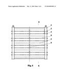
[0019]FIG. 1 is a schematic diagram of the structure of the invention.
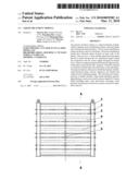
[0020]FIG. 2 is a schematic diagram of the side structure.
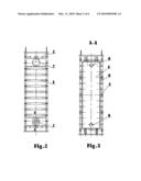
[0021]FIG. 3 is a schematic diagram of the A-A cutaway view in FIG. 1.
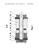
[0022]FIG. 4 is a schematic diagram of the enlarged B-B cutaway view in FIG. 1.
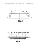
[0023]FIG. 5 is a schematic diagram of the power distribution panels.
[0024]FIG. 6 is a schematic diagram of the enlarged C-C cutaway view in FIG. 5.
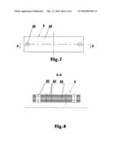
[0025]FIG. 7 is a schematic diagram of the double-sided electrode plates.
[0026]FIG. 8 is a schematic diagram of the enlarged D-D cutaway view in FIG. 7.
[0027]FIG. 9 is a schematic diagram of the intermediate electrical panels.
[0028]FIG. 10 is a schematic diagram of the enlarged E-E cutaway view in FIG. 9.
Whereas:
[0029]1-side plate, 2-power distribution panel, 21-insulation plate, 22-conductor, 22-1-connection part, 22-2-securing part, 22-3-electrical power distribution part, 23-collector plate, 24-electrode plate, 25-pipe guiding hole, 26-transition layer, 3-connection part, 4-double-sided electrode plate, 41-conductive plate, 42-electrode plate, 43-pipe guiding hole, 5-framework, 6-intermediate power distribution panel, 61-insulation plate, 62-conductor, 62-1-connection part, 62-2-securing part, 62-3-electrical power distribution part, 63-collector plate, 64-electrode plate, 65-pipe guiding hole, 66-transition layer, 7-flange, 8-liquid distributing pipe, 81-sealing head, 82-outer pipe, 83-inner pipe, 84-cover, 9-package, and 10-separator.
DETAILED DESCRIPTION OF PREFERRED EMBODIMENTS
[0030]The liquid treatment device of the present invention is shown in FIGS. 1 to 4, including the power distribution panels 2, electrode plates, and frameworks 5 with two side end plates 1.
[0031]As shown in FIG. 1, the two power distribution panels 2 are connected to the end plates 1 through the connector 3. Inside of the power distribution panels 2 is the electrode plate 24. The power distribution plates 2 are connected with the DC power supply through electrical wires. The power distribution panels 2 of the present invention may be conductive metal plates, and connect to the DC power supply through the electrical wires.
[0032]Alternatively, as shown in FIGS. 5 and 6, the power distribution plate can be made of the insulation plates 21 and sequentially on top of the inner side of the insulation plate 21, the conductive plate 22, the collector plate 23 and the electrode plate 24. There is also a transition layer 26 on the surface of the electrode plates 21. The conductor 22 is anchored to the securing part 22-2 on top of the transition layer 26 and the electrical power distribution part 22-3 on the surface of transition layer 26 through the connecting part 22-1 on the outside part of transition layer 26. Conductor 22 is connected to the DC power supply through the electrical wires. The collector plate 23 can be made of graphite foil to reduce manufacturing costs, and to provide good bonding affinity with the package 9 and the power distribution panels 2.
[0033]As shown in FIG. 4, more than two double-sided electrode plates 4 are stacked in between the two power distribution panels 2. The double-sided electrode plate 4, as shown in FIGS. 7 and 8, comprise a conductive plate 41 with electrode plates 42 bonded on the two sides of the conductive plate 41. The conductive plate 41 is made of graphite foil. The quantity of double-sided electrode plates to stack between the power distribution panels can be set in accordance with the treatment capacity. The present invention can use 2 to 10,000 pieces of double-sided electrode plates 4, preferably 10 to 1000 pieces, and most preferably 50 to 500 pieces between the power distribution panels. When the power is supplied to the power distribution panels 2, the double-sided electrode plates 4 set in between the distribution panels 2 are charged to start working. Because the power is supplied onto the power distribution panels 2 in series, it greatly reduces the operating current and simplifies the structure of power distribution system.
[0034]As shown in FIG. 4, there are separators 10 between the electrode plates 4 to separate the electrodes and to provide flow channels for liquid in between adjacent electrode plates 4. All the flow channels are connected to the inlet and outlet holes on the end plates 1.
[0035]As shown from FIGS. 1 to 3, the exposed parts of the power distribution panels 2, double-sided electrode plates 4 and the separator 10 are bonded by package 9. The package 9 plays the roles of physical supporting, sealing and insulation, and has also increased the mechanical strength of the modules.
[0036]To further enhance the handling capacity, as shown in FIG. 9-10, the present invention has one or more intermediate power distribution panels 6, which have electrode plates 64 on both sides, placed between the stacks of double-sided electrode plates 4. The intermediate power distribution panels 6 can be conductive metal plates and are connected to the DC power supply. In alternative, the intermediate power distribution panel 6 is comprised of the insulating substrate 61, the conductor 62 and collector plates 63. The conductors 62 and collector plates 63 are sequentially placed on both sides of the insulating substrates 61. There is also a transition layer 66 on the surface of the insulating substrates 61.
[0037]The conductor 62 is fixed on the securing part 62-2 on top of the transition layer 66 and the power distribution part 62-3 on the surface of transition layer 66 through the connecting part 62-1 on the outside part of transition layer 66. Conductor 62 is connected to the power supply through electrical wires, while the collector plate 63 uses graphite foil for its connection to the electrode plates 64. This configuration could also achieve a reduction in manufacturing costs, and provides a good bonding affinity to the package 9 and the intermediate power distribution panels 6. When the power is supplied to the power distribution panels 2 and intermediate power distribution panels 6, the current is also supplied to the two or more double-sided electrode plates located between the power distribution panel 2 and the intermediate power distribution panel 6.
[0038]As shown in FIGS. 1 and 4, the separator 10 has at least one layer of non-conductive materials with small holes or openings in the sheet like nets. The separator can be made into bags with the double-sided electrode plate 4 placed in the bag and the four sides sealed. The hole can be in various shapes with openings in the range of 0.01˜10 mm, preferably between 0.05˜5 mm, and most preferably between 0.1˜3 mm. Alternatively, the separator can be one or more plates with grooves, ripples, openings, or wings, or one or more soft panels such as sponge. Separator 10 shall provide liquid passage channels. Fillers and ion exchange resins can be placed in the channels to increase the turbulence of the flow. Turbulence helps mixing and can increase the treatment efficiency.
[0039]When the liquid to be processed flows through the flow channels between the electrode plates under the DC electric field, the ions, organic matter, suspended solids and colloidal particles in the liquid are removed. When the electrodes reach saturated or near the saturation point, the electrical circuit is shorted. Due to the disappearance of direct current electric field and the formation of the internal loop, the ions and charged particles stored in the electric double layer of the electrode surface return to the liquid flow channel and are discharged with the regeneration flow. The adsorbed organic matters are decomposed on the electrodes under the electric field to form carbon dioxide, inorganic acid, water, of which carbon dioxide and inorganic acid are stored in the electrodes in the form of acid radical, and are discharged with the washing liquid at the regeneration stage. After the ions and charged species are removed from the system, the electrodes are regenerated.
[0040]The liquid treatment modules of this invention have two liquid distributing pipes 8. The two liquid distributing pipes 8 penetrate the two end plates 1 through the inlet and outlet holes and are sealed and fastened to the end plates 1 by the flange 7. The liquid distributing pipes 8 allows the liquid to flow through the module from the top of the electrode plates to enter the liquid flow channel or from the two liquid distributing pipes passing through the liquid inlet and outlet holes on the side plates 1, the pipe guiding holes 25 of the power distribution panel 2, the pipe guiding holes 43 of the double-sided electrode plates 4, and are fastened to the end plates by flange 7.
[0041]When the modules are equipped with the intermediate power distribution panels, as shown in FIGS. 2 and 4, the two liquid distributing pipes 8 can pass through the inlet and outlet holes on the side plates 1, the pipe guiding holes 25 of the distribution panels, the pipe guiding holes 43 of the double-sided electrode plates 4, and the pipe guiding holes 65 of the intermediate power distribution panels 6. The two sides of the liquid distributing pipes 8 are connected to the side plates 1 through two flanges 7. This flow system allows liquid to flow from the liquid distributing pipes 8 directly into the flow channels between the electrodes.
[0042]As shown in FIG. 4, a liquid distributing pipe 8 comprises an outer pipe 82 and an inner pipe 83 which is located inside of the outer pipe 82 with the same axis. The outer pipe 82 has slit along the axis for liquid to flow in and out. The two outer pipes 82 have liquid flow slits in the opposite directions, one up and one down. The inner pipe 83 has the slit in opposite direction with its corresponding outer pipe 82. This design allows the adjustment of flow speed and the uniform distribution of the fluid flow. One end of the outer pipe 82 and inner pipe 83 are tightly connected by using the sealing head 81, the other end of the outer pipe 82 and the inner pipe 83 are connected and sealed by the cover 84. External pipes are connected to the inner pipe 83 through the cover 84. The liquid to be processed passes through inner pipe 83, outer pipe 82, and finally flows into the liquid channel between the electrodes.
[0043]The liquid treatment modules of present invention can be used to process liquids of various kinds including water, wine, fruit juices, beverages, dairy products and chemical wastes from various sources.
User Contributions:
comments("1"); ?> comment_form("1"); ?>Inventors list |
Agents list |
Assignees list |
List by place |
Classification tree browser |
Top 100 Inventors |
Top 100 Agents |
Top 100 Assignees |
Usenet FAQ Index |
Documents |
Other FAQs |
User Contributions:
Comment about this patent or add new information about this topic:
Images included with this patent application:
 |  |
 |  |
 |  |
 |
| Similar patent applications: | |
| Date | Title |
|---|---|
| 2012-10-18 | Fluid treatment device |
| 2012-05-03 | Fluid treatment systems |
| 2014-03-06 | Fluid treatment apparatus |
| 2009-09-17 | Liquid disinfectant apparatus |
| 2012-07-05 | Treatment sytems for fluids |
| New patent applications in this class: | |
| Date | Title |
|---|---|
| 2016-09-01 | Mechanical processing of oil sands |
| 2016-06-16 | Potential of zero charge-based capacitive deionization |
| 2016-06-09 | Electrical-storage type desalination electrode module, production method therefor and desalination device using same |
| 2015-10-15 | Electrolytic system and method for filtering an aqueous particulate suspension |
| 2015-03-05 | Apparatus for producing water for preparation of dialysis solution |
| Top Inventors for class "Chemistry: electrical and wave energy" | |
| Rank | Inventor's name |
|---|---|
| 1 | Vamsee K. Pamula |
| 2 | Michael G. Pollack |
| 3 | Adam Heller |
| 4 | Vijay Srinivasan |
| 5 | Li-Shiang Liang |