Patent application title: RAIL CAR SUSPENSION DAMPING
Inventors:
Joseph Wolinski (Metford, AU)
Philip Edward Morris (Hamilton, AU)
Assignees:
BRADKEN RESOURCES PTY. LIMITED
IPC8 Class: AB61F504FI
USPC Class:
1051984
Class name: Sprung bolster bolster movement dampened by snubber snubber biasing spring also supports bolster
Publication date: 2010-02-25
Patent application number: 20100043668
Inventors list |
Agents list |
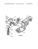
Assignees list |
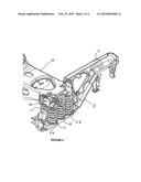
List by place |
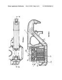
Classification tree browser |
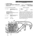
Top 100 Inventors |
Top 100 Agents |
Top 100 Assignees |
Usenet FAQ Index |
Documents |
Other FAQs |
Patent application title: RAIL CAR SUSPENSION DAMPING
Inventors:
Joseph Wolinski
Philip Edward Morris
Agents:
KENYON & KENYON LLP
Assignees:
BRADKEN RESOURCES PTY. LIMITED
Origin: SAN JOSE, CA US
IPC8 Class: AB61F504FI
USPC Class:
1051984
Patent application number: 20100043668
Abstract:
A freight rail car suspension has independent but co-operating springs; a
first spring is load carrying and has a variable damping function and a
second control spring operates on a friction shoe to apply a constant
damping component. A practical embodiment has a friction shoe engaged for
vertical displacement by the first spring which is mounted on a side
frame and the second spring is obliquely arranged between the bolster of
the bogie and the friction shoe, which has guides to cause it to move
into greater frictional engagement upon load being applied through the
spring. This arrangement provides a dual damping characteristic involving
both constant damping and variable damping forces.Claims:
1. A suspension damping system for a railcar bogie wherein there is a
first resilient system essentially in a load carrying and substantially
constant damping mode, and a second independent resilient system in
co-operating arrangement providing variable damping.
2. A system as claimed in claim 1, wherein when the system supports an unloaded railcar principally the damping is of a constant component and the minority component is variable damping and in a fully loaded situation the reverse is the case.
3. A suspension system for a railway car bogie comprising a first resilient structure with a line of action for damping movement and acting between a side frame and a friction shoe which engages the bolster, the line of action of the first resilient structure being along a first axis and a second resilient structure acting independently of the first resilient structure between the bolster and the friction shoe for providing damping, the second resilient structure acting on a second axis arranged at an acute angle to the first axis.
4. A suspension system as claimed in claim 3, wherein in use the first axis is arranged substantially vertically and the second axis is arranged at an oblique angle.
5. A suspension system as claimed in claim 4, wherein the oblique angle is about 30 degrees to 40 degrees to the horizontal.
6. A suspension system as claimed in claim 3, wherein the first resilient structure comprises a helical compression spring for mounting along the first axis and the second resilient structure comprises a second helical compression spring for mounting along the second axis.
7. A suspension system as claimed in claim 3, wherein when the system supports an unloaded railcar, principally the damping is of a constant component and the minority component is variable damping and in a fully loaded situation the reverse is the case.
8. A railcar bogie comprising a bolster connected to wheel-mounting side frames through a resilient dampened suspension, the suspension including a friction shoes displaceable mounted in the bolster for displacement to increase frictional engagement with a respective friction plate mounted on the side frame, a spring system associated with each friction shoe and comprising a first spring acting between the side frame and the friction shoe and a second spring acting between the bolster and the friction shoe.
9. A bogie as claimed in claim 8, wherein the first spring has load carrying and damping functions and is essentially acting on the friction shoe to cause variable damping effects and the second spring has a control function to control damping above and provide a constant damping effect.
10. A bogie as claimed in claim 8, wherein the first and second springs are chosen and mounted to achieve principally a constant damping component and a minority component of a variable damping component when the load is at the lower end of the operating load range, and when at the upper end of the operating load range the principal damping component is a variable damping component and a minority component is a constant damping component.
11. A bogie as claimed in claim 10, wherein the principal component of damping in each case is about 70% of the total damping.
12. A bogie as claimed in claim 8, wherein the first and second springs are helical compression springs, the first spring in use having a substantially vertical axis and the second spring being angled at about 35 degrees to the horizontal.
13. A bogie as claimed in claim 7, wherein the bogie has a resilient suspension structure between each side frame and the bolster and in each side frame there are two longitudinally spaced friction shoes and respective spring damping systems, the resilient suspension structure extending longitudinally on both sides of the spring damping systems.
14. A bogie as claimed in claim 7, wherein the bolster and the friction shoes have respective bosses for locating within end portions of the respective second springs of each spring system.
Description:
[0001]The present invention relates to suspensions for rail cars and in
particular is concerned with a resilient damping system for use in bogies
(or trucks) wherein a pivotal bolster extends between side frames and a
resilient suspension is located between the bolster and each of the side
frames.
[0002]There is a very great difference between the total weight of a freight rail car between its unloaded and loaded conditions. Typically the tare of a rail car is of the order of 20 tons and the car when fully loaded may be of the order of 120 tons. The design of the suspension can readily focus on carrying the loads effectively in either a loaded condition or an unloaded condition or some compromise may be reached, but the challenge is to provide an effective damping to the suspension when operating empty or loaded.
[0003]Generally designs are either based on constant damping or variable damping. Typically each bogie comprises a transversely extending bolster (on which the rail car body is pivotally mounted) and a pair of side frames mounting wheels (interconnected by axles)in suitable bearings. A spring suspension mounts the bolster on the side frames. Typically the suspension on each side frame comprises a multiplicity of parallel helical load springs together with damping springs supporting friction shoes (which are usually wedge shaped) and which transmit load from the damping springs to the friction shoe to urge its surface onto a vertical friction wear plate mounted on the bolster.
[0004]The design of the damping springs determines the damping effect to attenuate displacement of the side frames relative to the bolster. One approach is constant damping where the static column load does not vary with deflection.
[0005]Thus, with constant damping, the restoring force is constant with displacement in the system and when designed to suit the unloaded weight of the vehicle this can provide good performance in that configuration but is problematical when the vehicle is loaded, despite the designer seeking to select springs of appropriate performance and rating.
[0006]An alternative is a variable damping suspension where the restoring force varies with displacement. Such an approach is believed to be particularly useful for loaded vehicles operating at the loaded rating. However, when the vehicle is unloaded the system is problematical. Since empty rail cars often travel at greater speeds, an unsuitable damping system is a problem and instability, with consequent adverse wear on the railcars and the track, is likely.
[0007]Broadly the present invention is based on the concept of having separate independent but co-operating resilient systems to provide a blend of variable damping and constant damping.
[0008]In one aspect the present invention relies on the appreciation of using a dual system having a first resilient system essentially in a substantially variable damping mode, and a second independent resilient system in co-operating arrangement providing substantially constant damping. In practice though the range of loaded to empty the damping can vary from principally a variable damping component and a minor constant damping component to principally a constant damping component and a minor variable damping component.
[0009]In another aspect, the present invention may be considered as directed to a suspension system for a rail car bogie having a transverse bolster and side frames, the suspension system comprising a first resilient structure with a line of action for damping movement and acting between a side frame and a friction shoe which engages the line of action of the first resilient structure being the bolster along a first axis, and a second resilient structure acting independently of the first resilient structure between the bolster and the friction shoe for providing damping, the second resilient structure acting on a second axis arranged at an acute angle to the first axis.
[0010]In one embodiment, the first axis can be arranged substantially vertically and the second axis at an angle of about 30 degrees to about 40 degrees to the horizontal. Such systems can be arranged to provide dual damping functions i.e. a combination of inherently variable damping and constant damping components.
[0011]Conveniently the embodiment may be implemented using a first helical compression spring for mounting along the first axis and a second helical compression spring for mounting along the second axis.
[0012]Embodiments of the invention can be implemented in many ways and for example may offer the advantage of avoiding weakening the bolster as there is no need to provide a hole through the bolster and generally embodiments can be simpler to maintain than alternatives.
[0013]For illustrative purposes an embodiment of the invention will now be described with reference to the accompanying drawings, of which
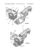
[0014]FIG. 1 is an isometric cut-away view of an embodiment of the invention partially assembled, the side frame being partially sectioned and the bolster being partially sectioned;
[0015]FIG. 2 is a view of the embodiment of FIG. 1 when assembled in a similar partially cut-away form;
[0016]FIG. 3 is an exploded view of the embodiment of FIGS. 1 and 2 showing principal components of the dual damping spring arrangement applied to the respective friction shoes;
[0017]FIG. 4 is an assembled view showing the components in part with the side frame sectioned longitudinally through its central plane and the bolster being transversely sectioned in the same central plane of the side frame;
[0018]FIG. 5 is a plan of the embodiment of FIG. 1 assembled; and
[0019]FIG. 6 is a longitudinal sectional view through the side frame along the line VI-VI of FIG. 5.
[0020]A railcar bogie comprises a pair of side frames connected to a bolster through respective spring suspension systems, the bolster being adapted to mount a railcar through a central pivotal mounting not shown in the drawings. At each end, each side frame mounts a wheel in a bearing the respective pairs of wheels being interconnected by axles. FIG. 1 shows an embodiment in which the bolster 10 is disposed for interconnection with a side frame 11 through a suspension system 12. The side frame mounts a pair of vertical wear plates 13 which confront respective sliding friction shoes 14 mounted in the bolster such that the resiliently applied force through a friction face 15 provides a damping function for the suspension.
[0021]In this case the suspension comprises a total of 9 spring elements with an outer line 16 comprising helical load compression springs and an inner line 17 comprising a similar line of load compression springs. The matrix of springs includes a centre spring 18 most clearly shown in FIG. 6 and in this embodiment comprising a smaller helical spring located within a larger helical spring to act in concert in resiliently supporting a load between the bolster and the side frame.
[0022]FIG. 3 in an exploded view which shows a variable load spring 20 for each shoe 14 and comprising a larger diameter outer spring 20A and a smaller diameter inner spring 20B, the springs being seated, as most conveniently shown in FIG. 6 between a base 22 of the shoe 14 and an support surface 24 in the side frame. This spring 20 is a variable load spring and provides a variable damping component to the overall suspension system by virtue of upward pressure under load on the shoe 14.
[0023]The shoe is also resiliently supported for receiving a constant damping force by a constant load control spring 26. As best shown in FIG. 6, the shoe has an angled interior portion 28 providing a boss for locating the upper end of the control spring and the lower end of the control spring is located over a confronting portion 30 formed in the bolster and thus guiding the shoe that its movement is confined to movement along a path at an angle of about 35 degrees to the horizontal.
[0024]When load is applied to the rail car, the bolster under load depresses the main load control springs and moves relatively downward to the side frame in a conventional manner. In a known variable control system a variable control spring such as 24 engages on the base of a wedge shaped friction shoe in a manner similar to that shown in the drawings but in the present embodiment there is the addition of the obliquely arranged constant load control spring 26.
[0025]This configuration thus provides two spring influences on the friction shoe and force from each spring urges the shoe to engage with a corresponding load on the vertical wear plate 13 on the side frame.
[0026]Embodiments of the invention will use suitably selected spring characteristics for the installation intended and its load carrying capacities. Typically the tare of a freight rail car is of the order of 20 tons but the fully loaded weight may well be of the order of 120 tons. Typically the spring characteristics and dimensions will be chosen such that in a tare condition principally the damping function component of force on each friction shoe is of the order of 70% to 80% of the total damping component from the constant load control spring 26 and the balance, a minority of the total component, is from the variable load spring 24. By contrast in the heavily laden condition, the springs are such that the reverse is the case and the constant load control spring contributes only 20% to 30% of the component total of force applied for damping and the balance is provided by the variable load spring.
[0027]Generally embodiments are intended to be implemented where at tare damping steadily increases with the load on the column from a tare condition to a fully laden condition.
[0028]It is believed this approach avoids the somewhat unsatisfactory compromise in known systems of either constant control or variable control of damping and in a practical and effective engineering arrangement permits effectively a dual damping phenomenon with variation in the damping through the load range to occur. If there is not appropriate damping of the spring suspension of a rail car in a particular condition, then the consequence can be instability of the cars as they travel in a railway system resulting in excessive wear of both the track and the bogie structure.
User Contributions:
comments("1"); ?> comment_form("1"); ?>Inventors list |
Agents list |
Assignees list |
List by place |
Classification tree browser |
Top 100 Inventors |
Top 100 Agents |
Top 100 Assignees |
Usenet FAQ Index |
Documents |
Other FAQs |
User Contributions:
Comment about this patent or add new information about this topic:
| People who visited this patent also read: | |
| Patent application number | Title |
|---|---|
| 20130028980 | CELL-POLYMER FIBER COMPOSITIONS AND USES THEREOF |
| 20130028979 | Stretch Marks Cream |
| 20130028978 | COMPOSITIONS AND METHODS FOR WOUND TREATMENT |
| 20130028977 | PHARMACEUTICAL POWDER COMPOSITION FOR INHALATION |
| 20130028976 | SPRAY-DRIED CRYSTALLINE ACTIVE INGREDIENT |
Images included with this patent application:
 |  |
 |  |
 |
| Similar patent applications: | |
| Date | Title |
|---|---|
| 2010-05-06 | Primary suspension device for a railway vehicle bogie |
| 2010-04-22 | Rail road freight car with damped suspension |
| 2011-01-20 | Railcar constant contact side bearing assembly |
| 2011-10-20 | Railcar primary suspension |
| 2009-10-22 | Rail car extension system |
| New patent applications in this class: | |
| Date | Title |
|---|---|
| 2016-03-03 | Railway car truck with friction damping |
| 2014-09-18 | Stabilized railway freight car truck |
| 2008-10-30 | Suspension for a rail vehicle |
| New patent applications from these inventors: | |
| Date | Title |
|---|---|
| 2010-09-16 | Container support for freight wagon |
| Top Inventors for class "Railway rolling stock" | |
| Rank | Inventor's name |
|---|---|
| 1 | James W. Forbes |
| 2 | Ajith Kuttannair Kumar |
| 3 | Tomasz Bis |
| 4 | Shunichi Nakao |
| 5 | Jamal Hematian |