Patent application title: CLEANING RAKER
Inventors:
Hung Chow (Zhongshan, CN)
Assignees:
XIAOTIAN (ZHONGSHAN) INDUSTRIAL CO., LTD.
IPC8 Class: AA46B1500FI
USPC Class:
15 211
Class name: Brushing, scrubbing, and general cleaning machines brushing
Publication date: 2010-02-25
Patent application number: 20100043155
Inventors list |
Agents list |
Assignees list |
List by place |
Classification tree browser |
Top 100 Inventors |
Top 100 Agents |
Top 100 Assignees |
Usenet FAQ Index |
Documents |
Other FAQs |
Patent application title: CLEANING RAKER
Inventors:
Hung Chow
Agents:
HAMRE, SCHUMANN, MUELLER & LARSON, P.C.
Assignees:
XIAOTIAN (ZHONGSHAN) INDUSTRIAL CO., LTD.
Origin: MINNEAPOLIS, MN US
IPC8 Class: AA46B1500FI
USPC Class:
15 211
Patent application number: 20100043155
Abstract:
The present invention provides a cleaning raker, which includes a raker
holder, a cleaning brush disposed on the raker holder, a dedusting driver
for driving the brush and a vibration device provided at a bottom of the
raker holder. The vibration device comprises a vibrating plate and a
vibrating driver for driving the vibrating plate. The vibrating plate is
connected to the vibrating driver. In use, dusts with static charge
around the raker holder are stirred along with vibration of the vibrating
plate under the drive of the vibrating driver. These dusts then are
cleaned with the brush easily, thus the cleaning efficiency is
significantly increased. Further, as cleaning some large bulk of dusts,
under the function of the vibrating plate, the vibration easily breaks
down these large bulks of dusts.Claims:
1. A cleaning raker, comprises:a raker holder;a cleaning brush disposed on
the raker holder;a dedusting driver for driving the brush; anda vibration
device provided at a bottom of the raker holder, the vibration device
comprising:a vibrating plate; anda vibrating driver for driving the
vibrating plate, the vibrating plate being connected to the vibrating
driver.
2. The cleaning raker of claim 1, wherein the vibrating device is a drive motor, an eccentric wheel being disposed on a power output shaft of the drive motor, the eccentric wheel being connected to the vibrating plate.
3. The cleaning raker of claim 1, wherein the vibrating device is a drive motor, an eccentric wheel being disposed on a power output shaft of the drive motor, the eccentric wheel pressing against the vibrating plate.
4. The cleaning raker of claim 1, wherein the vibrating driver is an electromagnetic valve vibrator, the electromagnetic valve vibrator comprising an electromagnetic oscillator plate and an electromagnetic coil, the electromagnetic coil being disposed in the electromagnetic oscillator plate, the electromagnetic oscillator plate being connected to the vibrating plate.
5. The cleaning raker of claim 1, wherein the vibrating device is an ultrasonic generator.
6. The cleaning raker of claim 1, wherein the vibrating plate is connected to the raker holder through a buffer suspension device.
7. The cleaning raker of claim 6, wherein the buffer suspension device is selected from the group consisting of: silica, spring, cylinder, and hydraulic cylinder.
Description:
TECHNICAL FIELD
[0001]This present invention relates to cleaning tools and, more particularly to a cleaning raker for dedusting.
BACKGROUND
[0002]At present, the cleaning raker in the market has a hand shank, movable pulleys, a brush and a dedusting driver. The hand shank is able to push and move the raker with the movable pulleys. The dedusting driver controls the brush to drive the brush to clean dusts. When cleaning dusts with the brush, the users just need to switch on the driver, then push and move the cleaning holder, the raker holder will move the brush and clean the dusts.
[0003]However, some problems restrict the use of the cleaning raker. For example, when a surface to be cleaned is a wool carpet, some dusts with static charge are easily adsorbed to the bottom of the carpet. Accordingly, it is difficult to completely clean these dusts with static charge due to interference of a wool layer on the surface of the carpet. This becomes a limitation to the clean function of the cleaning raker. Further, when cleaning a large bulk of dusts, as the brush is too soft, therefore, it is hard to clean the large bulk of dusts. Generally, such a large bulk of dusts is picked into a dustbin by hand, thus it brings inconvenience and low efficiency to cleaning operation.
[0004]Therefore, there is a need for a cleaning raker which can effectively improve cleaning efficiency.
SUMMARY
[0005]In accordance with an embodiment of the present invention, a cleaning raker is provided, which comprises a raker holder, a cleaning brush disposed on the raker holder, a dedusting driver for driving the brush and a vibration device provided at a bottom of the raker holder. The vibration device comprises a vibrating plate and a vibrating driver for driving the vibrating plate. The vibrating plate is connected to the vibrating driver.
[0006]Since the raker holder is provided with the vibrating device, dusts with static charge around the raker holder are stirred along with vibration of the vibrating plate under the drive of the vibrating driver. These dusts then are cleaned with the brush easily, thus the cleaning efficiency is significantly increased. As cleaning some large bulk of dusts, under the function of the vibrating plate, the vibration easily breaks down these large bulks of dusts, thereby preventing collecting such the large bulk of dusts by hand. This facilitates the clean of dusts and reduces the cleaning workload of the operator.
[0007]Other objects, advantages and novel features of the present invention will become more apparent from the following detailed description when taken in conjunction with the accompanying drawings.
BRIEF DESCRIPTION OF THE DRAWINGS
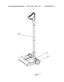
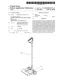
[0008]FIG. 1 is a structural, schematic view of a cleaning raker in accordance with a first embodiment of the present invention;
[0009]FIG. 2 is a side view of the cleaning raker in FIG. 1;
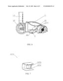
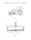
[0010]FIG. 3 is a partial cutaway, schematic view of the cleaning raker in FIG. 1, showing a vibrating device in the cleaning raker;
[0011]FIG. 4 shows a side structure of the vibrating device in FIG. 3;
[0012]FIG. 5 is a structural, schematic view of the vibrating device in FIG. 3;
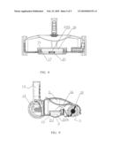
[0013]FIG. 6 is a partial cutaway, schematic view of another cleaning raker in accordance with a second embodiment of the present invention, showing another vibrating device;
[0014]FIG. 7 is a structural, schematic view of the vibrating device in FIG. 6;
[0015]FIG. 8 is a partial cutaway, schematic view of still another cleaning raker in accordance with a third embodiment of the present invention, showing still another vibrating device; and
[0016]FIG. 9 is a side view of the cleaning raker in FIG. 8.
DETAILED DESCRIPTION OF THE PREFERRED EMBODIMENTS
[0017]Objects, advantages and embodiments of the present invention will be explained below in detail with reference to the accompanying drawings. However, it is to be appreciated that the following description of the embodiment(s) is merely exemplary in nature and is no way intended to limit the invention, its application, or uses.
[0018]Referring to FIG. 1, FIG. 2 and FIG. 3, a cleaning raker in accordance with a first embodiment of the present invention is shown. The cleaning raker includes a raker holder 1, a cleaning brush 11 disposed on the raker holder 1 and a dedusting driver 12 for driving the brush 11. A vibration device 2 is provided at a bottom of the raker holder 1. The vibration device 2 includes a vibrating plate 21 and a vibrating driver 22 for driving the vibrating plate 21. The vibrating plate 21 is connected to the vibrating driver 22.
[0019]Specifically, an operating hand shaft 13 is disposed on the bottom of the raker holder 1. Movable pulleys 14 are disposed on the bottom of the raker holder 1 at one end of the hand shaft 13. In use, the user holds the hand shaft 13 by hand to control rotation of the movable pulleys 14 and thereby move the raker holder 1.
[0020]The brush 11 is located at an opposite side of the raker holder 1 relative to the movable pulleys 14. The opposite side is a front end, which is generally close to a ground region to be clean during cleaning. As shown in FIG. 2, the dedusting driver 12 includes a dedusting motor 121, a first gear 122 and a second gear 123. The first gear 122 is connected to the dedusting motor 121. The second gear 123 is disposed on the brush 11 and is connected to a transmission portion of the first gear 122. In this structure, the dedusting driver 12 drives the brush 11 to clean the dusts on ground.
[0021]As shown in FIG. 3, a bracket 15 is provided on the bottom of the raker holder 1. The bracket 15 forms a gap 16 for receiving the vibrating device 2 therein such that the vibrating plate 21 can closely face toward the ground.
[0022]Referring to FIG. 3 through FIG. 5, in the illustrated embodiment, the vibrating driver 22 is a drive motor 221. An eccentric wheel 222 is provided on a power output shaft of the drive motor 221. The eccentric wheel 222 is connected to the vibrating plate 21. As a power of vibration, the drive motor 221 drives the eccentric wheel 222 to turn. When turning, the eccentric wheel 222 periodically touches and presses against the vibrating plate 21, thereby achieving a periodical vibration of the vibrating plate 21.
[0023]Referring to FIG. 6 and FIG. 7, another cleaning raker in accordance with a second embodiment of the present invention is shown. The cleaning raker in this embodiment has another vibrating driver different from the vibrating driver in the first embodiment. In this embodiment, the vibrating driver 22 is an electromagnetic valve vibrator 223. The electromagnetic valve vibrator 223 includes an electromagnetic oscillator plate 224 and an electromagnetic coil 225. The electromagnetic coil 225 is disposed in the electromagnetic oscillator plate 224. The electromagnetic oscillator plate 224 is connected to the vibrating plate 21. In this embodiment, the electromagnetic oscillator plate 224 is a C-shaped plate with an open at one side thereof. The electromagnetic coil 225 is disposed in the C-shaped electromagnetic oscillator plate 224 vertically. After the electromagnetic coil 225 is switched on, the electromagnetic oscillator plate 224 generates periodical vibration which is transferred to the vibrating plate 21, thereby driving the vibrating plate 21 to vibrate.
[0024]Referring to FIG. 8 and FIG. 9, still another cleaning raker in accordance with a third embodiment of the present invention is shown. The cleaning raker in this embodiment has still another vibrating driver different from the vibrating driver in the above embodiments. In this embodiment, the vibrating driver 22 is an ultrasonic generator 226. As the ultrasonic generator 226 generates ultrasonic wave, the ultrasonic wave is transferred to the dusts through the vibrating plate 21, accordingly achieving a good vibrating cleaning effect.
[0025]In the above-mentioned embodiments, the vibrating plate 21 is connected to the raker holder 1, for example, through a suspension device 17. The suspension device 17 is configured to buffer the impact as the vibrating plate 21 is vibrating. In some embodiments, the suspension device 17 can be selected from the group consisting of: silica, spring, cylinder, and hydraulic cylinder and other similar buffering structure.
[0026]In these embodiments, since the raker holder 1 is provided with the vibrating device 2, dusts with static charge around the raker holder 1 are stirred along with vibration of the vibrating plate 21 under the drive of the vibrating driver 22. These dusts are raised up and then cleaned with the brush 11 easily, thus the cleaning efficiency is significantly increased. As cleaning some large bulk of dusts, under the function of the vibrating plate 21, the vibration easily breaks down these large bulks of dusts, thereby preventing collecting such large bulk of dusts by hand. This facilitates the clean of dusts and reduces the cleaning workload of the operator.
[0027]It is believed that the present embodiments and their advantages will be understood from the foregoing description, and it will be apparent that various changes may be made thereto without departing from the spirit and scope of the invention or sacrificing all of its material advantages, the examples hereinbefore described merely being preferred or exemplary embodiments of the invention.
User Contributions:
comments("1"); ?> comment_form("1"); ?>Inventors list |
Agents list |
Assignees list |
List by place |
Classification tree browser |
Top 100 Inventors |
Top 100 Agents |
Top 100 Assignees |
Usenet FAQ Index |
Documents |
Other FAQs |
User Contributions:
Comment about this patent or add new information about this topic:
| People who visited this patent also read: | |
| Patent application number | Title |
|---|---|
| 20150138553 | DEVICE FOR DETECTING SURFACE PLASMON AND POLARIZATION BY USING TOPOLOGICAL INSULATOR, METHOD OF MANUFACTURING THE DEVICE, AND METHOD OF DETECTING SURFACE PLASMON AND POLARIZATION |
| 20150138552 | APPARATUS AND METHOD FOR MEASURING PHYSIOLOGICALLY ACTIVE SUBSTANCE OF BIOLOGICAL ORIGIN |
| 20150138551 | APPARATUS AND METHOD FOR MEASURING PARTICLE SIZE DISTRIBUTION BY LIGHT SCATTERING |
| 20150138550 | APPARATUS AND METHOD FOR MEASURING PARTICLE SIZE DISTRIBUTION BY LIGHT SCATTERING |
| 20150138549 | TUNABLE LIGHT-GUIDE IMAGE PROCESSOR FOR MULTI-DIMENSIONAL IMAGING |
Images included with this patent application:
 |  |
 |  |
 |  |
| Similar patent applications: | |
| Date | Title |
|---|---|
| 2009-10-15 | Pool cleaning vehicle having improved intake port |
| 2011-10-20 | Cleaning disk for optical pickup head of optical disk drive |
| 2009-04-30 | Cleaning device for a water closet |
| 2009-04-30 | Cleaning apparatus, such as for synthetic grass |
| 2009-11-05 | Cleaning fabric and window screen cleaner |
| New patent applications in this class: | |
| Date | Title |
|---|---|
| 2022-05-05 | Constructions of automatic swimming pool cleaners |
| 2022-05-05 | Drive coupler for power scrubber |
| 2016-07-07 | Auto-cleansing apparatus |
| 2016-06-30 | Beauty device, body of beauty device, and head of beauty device |
| 2016-06-23 | Mechanical processing tool, and process and equipment for making a mechanical processing tool |
| New patent applications from these inventors: | |
| Date | Title |
|---|---|
| 2010-03-18 | Steam iron |
| 2010-02-25 | Steam iron |
| Top Inventors for class "Brushing, scrubbing, and general cleaning" | |
| Rank | Inventor's name |
|---|---|
| 1 | Wayne Ernest Conrad |
| 2 | Xavier Boland |
| 3 | Helmut Depondt |
| 4 | Robert Moskovich |
| 5 | James Dyson |