Patent application title: Roof top wind generator
Inventors:
Glen Kane (Rapid City, SD, US)
IPC8 Class: AE04D1318FI
USPC Class:
521731
Class name: Static structures (e.g., buildings) combined
Publication date: 2010-02-18
Patent application number: 20100037541
Inventors list |
Agents list |
Assignees list |
List by place |
Classification tree browser |
Top 100 Inventors |
Top 100 Agents |
Top 100 Assignees |
Usenet FAQ Index |
Documents |
Other FAQs |
Patent application title: Roof top wind generator
Inventors:
Glen Kane
Agents:
Glen Kane
Assignees:
Origin: RAPID CITY, SD US
IPC8 Class: AE04D1318FI
USPC Class:
521731
Patent application number: 20100037541
Abstract:
The roof top wind generator is design to mount on the ridge of a roof to
capture the wind energy without any obtrusive towers or unpleasant
looking structures or equipment. The basic design is a multi-fin turbine,
built into a roof cap design.
When the wind hits the flat surface of the pitched roof it moves up the
roof to the peak much like the wind currents over a airplane wing. When
this happens the wind speed is increased to nearly double the velocity at
the peak. The roof top wind generator captures that increased wind
velocity as it moves over the peak to increases the effectiveness of the
wind generator.Claims:
1. This roof top wind generator is unique because it becomes nearly
invisible. Many areas have building codes or ordinances that disallow
traditional wind generators or turbines due to the unsightly nature of
them. The roof top wind generator system may be allowed in these areas
because they are virtually invisible. Therefore, it is a vertically
invisible wind generator system.
2. When the wind hits the flat surface of the pitched roof it moves up the roof to the peak much like the wind currents over a airplane wing. When this happens the wind speed is increased to nearly double the velocity at the peak. The roof top wind generator captures that increased wind velocity as it moves over the peak. This in turn increases the turbine speed to near double of what it would be away from the roof. This situation in turn nearly doubles the effectiveness of the wind generator.
Description:
[0001]The roof top wind generator is design to mount on the ridge of a
roof to capture the wind energy without any obtrusive towers or
unpleasant looking structures or equipment. The roof top wind generator
will come in lengths as short as 2 feet and as long as 10 feet. The basic
design is a multi-fin turbine sometimes referred to as a squirrel cage,
built in a roof cap design with sheet metal. The units can be painted or
a pre-finished color can be applied by the manufacture. These sections
are designed to interlock and plug into each other and to adapt to any
ridge length. This system can be used in place of other ridge cap roofing
systems. It can also be added as a retrofit as long as it is fastened to
manufactures specifications. This system can be adapted to mount on most
any pitch of roof in commercial or residential applications.
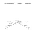
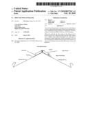
[0002]FIG. 1.
[0003]The Flashing is a one piece design that goes over the peak in a seamless fashion and laps over the roofing material at the lower edge to create a leak proof system.
[0004]FIG. 2.
[0005]The opening dimension at the lower edge of the roof top structure where the wind enters will be a minimum of 3 inches and can be ordered up to 12 inches.
[0006]FIG. 3.
[0007]The multi-fin turbine size is determined by the opening size and ranges from 3 to 12 inches.
[0008]FIG. 4.
[0009]The vertical pieces that attach the lower flashing to the upper shroud are designed as fins to keep structural integrity, keep birds and other obstruction out of the turbine and also help direct wind currents.
[0010]FIG. 5.
[0011]The Upper Shroud is also made from sheet metal in a one piece design to protect the Turbine and direct and capture wind flows.
User Contributions:
comments("1"); ?> comment_form("1"); ?>Inventors list |
Agents list |
Assignees list |
List by place |
Classification tree browser |
Top 100 Inventors |
Top 100 Agents |
Top 100 Assignees |
Usenet FAQ Index |
Documents |
Other FAQs |
User Contributions:
Comment about this patent or add new information about this topic:
| People who visited this patent also read: | |
| Patent application number | Title |
|---|---|
| 20130163143 | MULTILAYER CERAMIC ELECTRONIC COMPONENT AND METHOD OF MANUFACTURING THE SAME |
| 20130163142 | SURFACE MOUNT COMPONENT HAVING MAGNETIC LAYER THEREON AND METHOD OF FORMING SAME |
| 20130163141 | INPUT CIRCUIT FOR ALTERNATING CURRENT SIGNAL, AND MOTOR STARTER INCLUDING THE SAME |
| 20130163140 | METHOD AND A DEVICE FOR ATTRACTING MAGNETIC PARTICLES TO A SURFACE |
| 20130163139 | VARIABLE BREAKDOWN TRANSIENT VOLTAGE SUPPRESSOR |
Images included with this patent application:
 |  |
 |
| Similar patent applications: | |
| Date | Title |
|---|---|
| 2009-01-01 | Wind energy plant tower |
| 2010-05-27 | Roof ridge wind turbine |
| 2011-09-01 | Roof with ridge vent brace |
| 2013-07-04 | Rooftop snow stop apparatus |
| New patent applications in this class: | |
| Date | Title |
|---|---|
| 2019-05-16 | Adjustable concealed heating and cooling system |
| 2019-05-16 | Hybrid operating room for combined surgical and fixed imaging services in an ambulatory surgical center |
| 2016-12-29 | Method and apparatus for positioning heating elements |
| 2016-07-07 | Expandable, modular information technology facility providing efficient expansion of distributed power supply system |
| 2016-06-16 | Heat panel and fastener system |
| Top Inventors for class "Static structures (e.g., buildings)" | |
| Rank | Inventor's name |
|---|---|
| 1 | Darko Pervan |
| 2 | Gregory F. Jacobs |
| 3 | Husnu M. Kalkanoglu |
| 4 | Ronald P. Hohmann, Jr. |
| 5 | Mark Cappelle |