Patent application title: SURVEILLANCE SYSTEM AND SURVEILLANCE METHOD THEREOF
Inventors:
Shiao-Wei Lee (Tu-Cheng, TW)
Assignees:
HON HAI PRECISION INDUSTRY CO., LTD.
IPC8 Class: AH04N718FI
USPC Class:
348143
Class name: Television special applications observation of or from a specific location (e.g., surveillance)
Publication date: 2010-02-11
Patent application number: 20100033568
Inventors list |
Agents list |
Assignees list |
List by place |
Classification tree browser |
Top 100 Inventors |
Top 100 Agents |
Top 100 Assignees |
Usenet FAQ Index |
Documents |
Other FAQs |
Patent application title: SURVEILLANCE SYSTEM AND SURVEILLANCE METHOD THEREOF
Inventors:
SHIAO-WEI LEE
Agents:
PCE INDUSTRY, INC.;ATT. Steven Reiss
Assignees:
HON HAI PRECISION INDUSTRY CO., LTD.
Origin: CITY OF INDUSTRY, CA US
IPC8 Class: AH04N718FI
USPC Class:
348143
Patent application number: 20100033568
Abstract:
A method for surveillance is disclosed. Firstly, video of an area is
captured. The video includes a first image and a second. Each image is
subdivided into a number of subdivisions. A contrast value matrix is then
calculated for each image by calculating a contrast value for each
subdivision. A compared value matrix of the second image is calculated by
comparing each element of the contrast value matrix associated with the
current image with a corresponding element of the contrast value matrix
associated with the prior image. Next, the compared value matrix is
weighted using a preset weight matrix to locate the movement in the
second image. Finally, the aim of capturing is adjusted based upon the
location of movement.Claims:
1. A surveillance system comprising:a video capturing unit capable of
capturing video of an area, the video comprises a first image and a
second image;a detecting unit configured for subdividing each image into
a plurality of subdivisions and calculating a contrast value for each
subdivision to produce a contrast value matrix associated with the
corresponding image;a comparing unit configured for comparing each
element of the contrast value matrix associated with the second image
with a corresponding element of the contrast value matrix associated with
the first image and determining a compared value matrix associated with
the second image;a calculating unit configured for weighting the compared
value matrix using a preset weight value matrix to determine the location
of movement in the second image; anda controlling unit configured for
adjusting aim, focus or the aim and the focus of the video capturing
unit.
2. The surveillance system as claimed in claim 1, wherein the video capturing unit comprises a lens and an image sensor.
3. The surveillance system as claimed in claim 2, where in the image sensor is selected from the group consisting of a charge-coupled device and a complementary metal oxide semiconductor.
4. The surveillance system as claimed in claim 1, wherein the detecting unit counts the number of pixels whose values are greater than a predetermined value for each subdivision, and calculates the ratio of the total number of pixels to the counted number for each subdivision, the calculated ratios are the contrast values of the subdivisions.
5. The surveillance system as claimed in claim 1, wherein an element of the comparing value matrix is valued as `0` if the difference between two corresponding compared elements is smaller than a predetermined threshold and otherwise is valued as `1`.
6. The surveillance system as claimed in claim 1, wherein the preset weight value matrix is:{A11:1 A12:2 A13:1}{A21:2 A22:4 A23:2},{A31 1 A32 2 A33 :1}the calculating unit weighting a comparing value matrix C according to the following formula:Rmn=B.sub.(m-1)(n-1)×W11+B.sub.(m-1)n×W.sub- .12+B.sub.(m-1)(n+1)×W13+Bm(n-1)×W21+Bmn.t- imes.W22+Bm(n+1)×W23+B.sub.(m+1)(n-1)×W31+- B.sub.(m+1)n×W32+B.sub.(m+1)(n+1)×W33 where m and n are natural numbers, Rmn is an element of a weighted matrix at the intersection of m line and n row, Bmn is an element of the comparing value matrix at the intersection of m line and n row.
7. The surveillance system as claimed in claim 1, wherein the controlling unit is configured to adjust the aim, focus or the aim and focus of the video capturing unit based upon the determination of the calculating unit.
8. The surveillance system as claimed in claim 7, wherein the controlling unit is capable of keeping a moving object in the captured video.
9. A surveillance method comprising:capturing video of an area, the video comprises a first image and a second image;subdividing each image into a plurality of subdivisions and calculating a contrast value for each subdivision;producing a contrast value matrix for each image;comparing each element of the contrast value matrix of the second image with a corresponding element of the contrast value matrix of the first image and thereby determining a compared value matrix associated with the second image;weighting the compared value matrix using a preset weight matrix to determine where movement is located in the second image; andadjusting the aim, focus or aim and focus, of capturing to include the movement.
10. A surveillance method comprising:providing a surveillance system comprising:a video capturing unit capable of capturing video of an area, the video comprises a first image and a second image;a detecting unit configured for subdividing each image into a plurality of subdivisions and calculating a contrast value for each subdivision to produce a contrast value matrix associated with the corresponding image;a comparing unit configured for comparing each element of the contrast value matrix associated with the second image with a corresponding element of the contrast value matrix associated with the first image and determining a compared value matrix associated with the second image;a calculating unit configured for weighting the compared value matrix using a preset weight value matrix to determine the location of movement in the second image; anda controlling unit configured for adjusting aim, focus or the aim and the focus of the video capturing unit;capturing the video of an area using the video capturing unit;subdividing each image into a plurality of subdivisions and calculating the contrast value for each subdivision using the detecting unit;producing the contrast value matrix for each image using the detecting unit;comparing each element of the contrast value matrix of the second image with a corresponding element of the contrast value matrix of the first image and thereby determining the;weighting the compared value matrix using the preset weight matrix to determine where movement is located in the second image using the calculating unit; andadjusting the aim, focus or aim and focus, of capturing to include the movement using the controlling unit.
Description:
BACKGROUND
[0001]1. Technical Field
[0002]The present disclosure relates to surveillance systems and, particularly, to a surveillance system capable of automatically tracking a moving object and a surveillance method thereof.
[0003]2. Description of the Related Art
[0004]Current surveillance systems typically require manual adjustments to track moving object(s). This is inconvenient.
[0005]Therefore, it is desirable to provide a surveillance system and a surveillance method thereof, which can overcome the above-mentioned problem.
BRIEF DESCRIPTION OF THE DRAWINGS
[0006]FIG. 1 is functional block diagram of a surveillance system, according to an exemplary embodiment.
[0007]FIG. 2 is a schematic view showing the working principle of the surveillance system of FIG. 1.
[0008]FIG. 3 is flowchart of a surveillance method, according to another exemplary embodiment.
DETAILED DESCRIPTION OF THE EMBODIMENTS
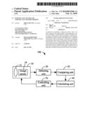
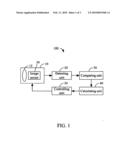
[0009]Referring to FIG. 1, a surveillance system 100, according to an exemplary embodiment, includes a video capturing unit 10, a detecting unit 20, a comparing unit 30, a calculating unit 40, and a controlling unit 50. The video capturing unit 10 is configured for capturing video of an area. The video includes a number of consecutive images. The detecting unit 20 is configured for subdividing each image into a number of subdivisions and calculating a contrast value for each subdivision to produce a contrast value matrix associated with the corresponding image. The comparing unit 30 is configured for comparing each element of the contrast value matrix associated with a current image with a corresponding element of the contrast value matrix associated with a prior image and thereby determining a comparing value matrix associated with the current image. An element of the comparing value matrix is valued as `0` if the difference between two corresponding compared elements is smaller than a predetermined threshold or otherwise is valued as `1`. The calculating unit 40 is configured for weighting the comparing value matrix associated with the current image using a preset weight value matrix to determine where a moving object is located in the current image. The controlling unit 50 is configured for adjusting the aim of the video capturing unit 10, based upon the determination of the calculating unit 40, so that the moving object is included in a subsequent image (see below).
[0010]The video capturing unit 10 includes a lens 12 and an image sensor 14. The image sensor 14 can be a charge-coupled device (CCD) or a complementary metal oxide semiconductor (CMOS).
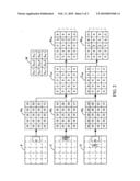
[0011]Referring to FIG. 2, in this embodiment, the surveillance system 100 is considered to be configured to surveil an interior entrance area of a building. Accordingly, the video capturing unit 10 is initially aimed to capture video of a doorway of the entrance area. Exemplarily, the video includes three images P, C, S.
[0012]In the embodiment, the detecting unit 20 subdivides each image into 4×5 subdivisions. Further, the detecting unit 20 counts the number of pixels whose values are greater than a preset value for each subdivision, and calculates the ratio of the total pixel number to the counted number for each subdivision. The calculated ratios of the subdivisions constitute the contrast value matrix associated with the corresponding image. In this embodiment, corresponding to the images P, C, S, three contrast value matrices MP, MC, MS are produced by the detecting unit 20.
[0013]The predetermined threshold used by the comparing unit 30 in this embodiment is 0.05 m, where m is the value of the element of the contrast value matrix associated with the prior image. Corresponding to the three contrast value matrices MP, MC, MS, in this embodiment, two comparing value matrices CMC (taking P as the prior image and C as the current image), CMS (taking C as the prior image and S as the current image) are calculated by the comparing unit 30. In principle, each element of the comparing value matrix can describe whether the contrast change of the corresponding subdivision between the current image and the prior image is acceptable. If yes, it is deemed that no moving object enters into the corresponding subdivision and is labeled as `0`. If no, it is deemed that the corresponding subdivision is entered by the moving object and is labeled as `1`.
[0014]The weight value matrix used in this embodiment is W. The calculating unit 40 weights a comparing value matrix C according to the following formula:
Rmn=B.sub.(m-1)(n-1)×W11+B.sub.(m-1)n×W12+B.sub- .(m-1)(n+1)×W13+Bm(n-1)×W21+Bmn×W.su- b.22+Bm(n+1)×W23+B.sub.(m+1)(n-1)×W31+B.sub.(m+- 1)n×W32+B.sub.(m+1)(n+1)×W33
Where, m=1, 2, 3, 4, n=1, 2, 3, 4, 5, Rmn is an element of a weighted matrix at the intersection of m line and n row, Bmn is an element of the comparing value matrix at the intersection of m line and n row. In this embodiment, corresponding to the comparing value matrices CMS, CMS, two weighted comparing value matrices WMS, WMC are calculated by the calculating unit 40.
[0015]In principle, the weight value matrix is an edge detecting operator. Therefore, as shown in FIG. 2, after weighting, the calculating unit 40 can recognize where the moving object is located (marked by the dashed line frame). Thereby the controlling unit 50 can adjust the aim of the lens 12 to always include the moving object therein, based upon the recognition of the calculating unit 40.
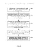
[0016]Referring to FIG. 3, a surveillance method, according to another exemplary embodiment, can be exemplarily implemented by the surveillance system 100 and includes the following steps S202-210.
[0017]S202: capturing video of an area. The video includes a number of consecutive images, e.g., a prior image, a current image, and a subsequent image. This step can be carried out by the video capturing unit 10.
[0018]S204: subdividing each image into a number of subdivisions and calculating a contrast value for each subdivision to produce a contrast value matrix associated with the corresponding image. This step can be carried out by the detecting unit 20.
[0019]S206: comparing each element of the contrast value matrix associated with the current image with a corresponding element of the contrast value matrix associated with the prior image and thereby determining a comparing value matrix associated with the current image. This step can be carried out by the comparing unit 30.
[0020]S208: weighting the comparing value matrix using a preset weight value matrix to determine where a moving object is located in the current image. This step can be carried out by the calculating unit 40.
[0021]S210: adjusting the aim of the video capturing unit 10 to keep the moving object included in the subsequent image, based upon the determination of the weighting step. This step can be carried out by the controlling unit 50.
[0022]While the disclosure has been described by way of example and in terms of preferred embodiment, it is to be understood that the disclosure is not limited thereto. To the contrary, it is intended to cover various modifications and similar arrangements, which would be apparent to those skilled in the art. Therefore, the scope of the appended claims should be accorded the broadest interpretation so as to encompass all such modifications and similar arrangements.
[0023]It is also to be understood that above description and any claims drawn to a method may include some indication in reference to certain steps. However, the indication used is only to be viewed for identification purposes and not as a suggestion as to an order for the steps.
User Contributions:
comments("1"); ?> comment_form("1"); ?>Inventors list |
Agents list |
Assignees list |
List by place |
Classification tree browser |
Top 100 Inventors |
Top 100 Agents |
Top 100 Assignees |
Usenet FAQ Index |
Documents |
Other FAQs |
User Contributions:
Comment about this patent or add new information about this topic:
Images included with this patent application:
 |  |
 |  |
| Similar patent applications: | |
| Date | Title |
|---|---|
| 2013-02-28 | Surveillance system and controlling method thereof |
| 2012-09-27 | Imaging system for immersive surveillance |
| 2012-12-27 | Surveillance camera with rapid shutter activation |
| 2013-02-14 | Apparatus and method for using augmented reality vision system in surgical procedures |
| 2010-11-11 | Surveillance image denial verification |
| New patent applications in this class: | |
| Date | Title |
|---|---|
| 2022-05-05 | Method for monitoring drug preparation |
| 2019-05-16 | Doorbell camera with battery at chime |
| 2019-05-16 | Information processing system, information processing method, and program |
| 2019-05-16 | Information processing system, information processing method, and program |
| 2019-05-16 | Method for controlling a monitoring camera |
| New patent applications from these inventors: | |
| Date | Title |
|---|---|
| 2009-06-11 | Method for displaying on-screen display |
| Top Inventors for class "Television" | |
| Rank | Inventor's name |
|---|---|
| 1 | Canon Kabushiki Kaisha |
| 2 | Kia Silverbrook |
| 3 | Peter Corcoran |
| 4 | Petronel Bigioi |
| 5 | Eran Steinberg |