Patent application title: BUILT-IN SLIDING ROTATING ELEMENT FOR MODULAR CORNER CABINETS
Inventors:
Rossano Compagnucci (Osimo, IT)
Assignees:
COMPAGNUCCI HOLDING S.P.A.
IPC8 Class: AA47B7700FI
USPC Class:
312245
Class name: Supports: cabinet structure mounted on wall, ceiling or spaced panels
Publication date: 2010-02-11
Patent application number: 20100033068
Inventors list |
Agents list |
Assignees list |
List by place |
Classification tree browser |
Top 100 Inventors |
Top 100 Agents |
Top 100 Assignees |
Usenet FAQ Index |
Documents |
Other FAQs |
Patent application title: BUILT-IN SLIDING ROTATING ELEMENT FOR MODULAR CORNER CABINETS
Inventors:
Rossano Compagnucci
Agents:
Robert M. Gamson, Esquire;Hodes, Pessin & Katz, P.A.
Assignees:
COMPAGNUCCI HOLDING S.P.A.
Origin: TOWSON, MD US
IPC8 Class: AA47B7700FI
USPC Class:
312245
Patent application number: 20100033068
Abstract:
The present invention relates to a wall cabinet for modular kitchens made
up of a first bottom (1), an identical top (2), a back panel (4) and two
identical lateral sides (3), in which at least one metal section (6, 7,
100) is interposed between the lower sides (3a), being provided with a
lower longitudinal groove (6b, 60b) designed to receive and support
underthecabinet accessories and/or a longitudinal groove (7b, 70b)
designed to receive a LED light (8).Claims:
1. Wall cabinet for modular kitchens of the type formed of a first bottom
(1), an identical top (2), two identical lateral sides (3), a back panel
(4) and possibly a front door (5), characterised in that at least one
metal section (6, 7, 100) is interposed between the lower sides (3a) of
the opposite pair of lateral sides (3), provided with a lower,
longitudinal groove (6b, 60b) to receive and support under the cabinet
accessories, and/or a longitudinal groove (7b, 70b) designed to receive a
LED light bar (8).
2. Wall cabinet for modular kitchens as claimed in claim 1, characterised in that a metal section (6, 100) is interposed at the height of the back edge (1a) of the bottom (1) between the lower sides (3a) of the opposite pair of lateral sides (3), being provided with a top longitudinal groove (6a, 60a) that receives the lower edge (4a) of the back panel (4).
3. Wall cabinet for modular kitchens as claimed in claim 1, characterised in that a metal section (7) is interposed at the height of the front side (1b) of the bottom (1) between the lower sides (3a) of the opposite pair of lateral sides (3), being provided with a lower longitudinal groove (6a, 60a) that receives the LED light bar (8).
4. Wall cabinet for modular kitchens as claimed in claim 1, characterised in that the following components are interposed between the lower sides (3a) of the opposite pair of lateral sides (3):a first metal section (6) in parallel position to the back edge (1a) of the bottom (1) provided with a lower longitudinal groove (6b) designed to receive and support the under the cabinet accessories;a second metal section (7) in parallel position to the front edge (1b) of the bottom (1) provided with a lower longitudinal groove (7b) designed to receive a lighting bar with LED's (8).
5. Wall cabinet for modular kitchens as claimed in claim 4, characterised in that the first metal section (6) is provided on the front with a longitudinal shelf (6d) having a perfectly horizontal direction and in that the second metal section (7) is provided on the back with a longitudinal shelf (7d) having a perfectly horizontal direction.
6. Wall cabinet for modular kitchens as claimed in claim 4, characterised in that:the second metal section (7) is provided on the front with a longitudinal groove (7a) with gasket (9).
7. Wall cabinet for modular kitchens as claimed in claim 1, characterised in that the only one metal section (100) is interposed between the lower sides (3 a) of the opposite pair of lateral sides (3), in parallel position to the back edge (1a) of the bottom (1) provided with:a lower pair of parallel longitudinal grooves, the one (60b) facing the back of the cabinet, designed to receive and support under the cabinet accessories, and the other (70b) facing the front of the cabinet (M) designed to receive the LED light bar (8);a top groove (60a) facing the back of the cabinet designed to receive the lower edge (4a) of the back panel (4);a front longitudinal groove (60d) designed to connect the section (100) with the bottom (1).
8. Wall cabinet for modular kitchens as claimed in claim 1, characterised in that the groove (6b, 60b) has an overturned U-shaped cross-section, with opening having reduced width because of a longitudinal sloping end (6c) obtained on the front edge of the groove (6b, 60b) sloping towards the inside of ht groove (6b, 60b).
9. Wall cabinet for modular kitchens as claimed in claim 1, characterised in that the sections (6, 7, 100) are firmly fixed inside the lateral sides (3) of the cabinet (M).
10. Wall cabinet for modular kitchens as claimed in claim 1, characterised in that the lower grooves (7b, 70b) have an overturned U-shaped cross-section with corners internally provided with a longitudinal groove (7e) where a longitudinal tooth (D) obtained in external position on the LED light bar (8) is elastically snap-fitted.
11. Wall cabinet for modular kitchens as claimed claim 10, characterised in that the light bar (8) is formed of a strip (8a) that supports a close series of LED's (L) and the relevant electrical circuit, with on/off switch (1), and a case (8b) that houses, covers, insulates and protects the strip (8a).
12. Wall cabinet for modular kitchens as claimed claim 11, characterised in that the case (8b) is suitably shaped and dimensioned in order to be snap-fitted inside the longitudinal groove (7b, 70b) and in that it has a U-shaped cross-section with a horizontal base (LO) and two lateral borders (SL), in which the horizontal base (LO) has a closed series of holes (F) designed to receive the close series of LED's (L) and the on/off switch (1), while the edge of the lateral borders (SL) is provided externally with a longitudinal tooth (D) designed to be received into the longitudinal groove (7e).
Description:
[0001]The present patent application for industrial invention relates to a
wall cabinet for modular kitchens provided on the bottom with at least
one metal section with box-shaped structure, which is used to contain or
hang accessories, such as for example LED light bars or underthecabinet
elements, such paper towel roll holders, basket holders, hooks for ladles
holders, forks holders, etc. Wall cabinets for modular kitchen have a
standardised structural configuration, which comprises a parallelepiped
body, possibly closed by a front door, and composed of two identical
horizontal bottoms, a lower and an upper one, and two identical lateral
sides, a right and a left one, with the interposition of a thin back
panel used for covering purposes, without a bearing function, unlike the
bottoms and the sides, which are mainly composed of rigid sturdy boards
made of laminated chipboard or medio-densit wood.
[0002]It must be noted that the rigid connection between the two sides is obtained by means of the two bottoms, which are normally screwed and/or glued between the sides.
[0003]Currently, the aforementioned underthecabinet accessories are fixed to the wall directly or under the bottom of the cabinet close to the back side, using traditional fixing means, such as screws or glue.
[0004]In both cases the fixing means require mounting and dismounting operations that must be performed by specialised personnel.
[0005]When the said accessories and relevant support means are removed, indelible marks are left by the screws or the glue on the wall or the bottom of the wall cabinet.
[0006]The purpose of the present invention is to find a remedy to the latter problem, by devising a new model of cabinet for modular kitchens, which is provided on the bottom with at least one metal section with box-shaped structure used to house or hang the said accessories.
[0007]An additional purpose of the present invention is to devise a LED light bar that is inserted into the said metal section in a simple, easy way in order to sell the said bar separately after purchasing the wall cabinet, leaving the final user the task and satisfaction to install the said light bar personally.
[0008]These and other purposes have been achieved by the present invention, as described in the main claim and in the following dependent or sub-dependent claims.
[0009]According to the preferred embodiment, the wall cabinet of the invention has two lateral sides and two bottoms, with the interposition of two box-shaped metal sections between them, the front one being suitably shaped to house a LED light bar, and the back one being suitably shaped to hook the aforementioned underthecabinet accessories.
[0010]When the accessories and light bar are removed, the bottom of the wall cabinet does not show anti-aesthetical marks that alter the surface finish, since the metal sections are integrated in the cabinet structure with a decorative function, being practically composed of two aluminium strips that aesthetically finish the front and the back side of the bottom of the cabinet.
[0011]Finally, it must be noted that the metal section designed to be positioned in adjacent position to the back side of the bottom of the cabinet is provided with a longitudinal groove with upward opening, designed to be used as housing for the lower edge of the back panel, which is recessed in the current models of cabinets into a suitable notch obtained on the upper side of the bottom of the wall cabinet.
[0012]For major clarity the description of the wall cabinet of the invention continues with reference to the enclosed drawings, which only have an illustrative, not limiting purposes, whereby:
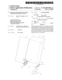
[0013]FIG. 1 is an axonometric bottom view of the wall cabinet of the invention, in which the bottom of the wall cabinet is exploded to show its constructive parts;
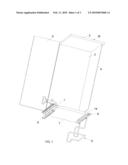
[0014]FIG. 2 is an enlarged exploded view of the bottom of the wall cabinet of the invention;
[0015]FIGS. 2A and 2B are two enlarged views of FIG. 2;
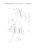
[0016]FIG. 3 is an enlarged exploded view of the bottom of the wall cabinet of the invention according to an alternative constructive embodiment.
[0017]With reference to FIGS. 1 and 2, the wall cabinet (M) of the invention comprises a first bottom (1), an identical top (2), two identical lateral sides (3), a back panel (4) and a front door (5).
[0018]A first metal section (6), preferably made of aluminium, is interposed between the lower sides (3a) of the opposite pair of lateral sides (3), at the height of the back edge (1a) of the bottom (1), being provided with a top longitudinal groove (6a) and a bottom longitudinal groove (6b).
[0019]The first groove (6a) has a U-shaped cross-section that exactly houses the lower edge (4a) of the back panel (4), while the second groove (6b) has an overturned U-shaped cross-section, whose opening has a reduced width because of a longitudinal sloping end (6c) obtained on the front edge of the groove (6b) sloping towards the inside of the groove (6b).
[0020]The first metal section (6) is provided on the front side with a longitudinal shelf (6d) having a perfectly horizontal direction, which is designed to connect the first metal section (6) and the back edge (1 a) of the bottom (1).
[0021]FIG. 2 shows an underthecabinet element consisting in an ordinary paper towel roll holder (S) made of bent wire; the holder (S) is provided with two suitable hooks (G) that are inserted from down upwards inside the second groove (6b) and be hooked to the sloping end (6c).
[0022]A second metal section (7), preferably made of aluminium, is interposed between the lower sides (3a) of the opposite pair of lateral sides (3), on the front side (1b) of the bottom (1), being provided with a lower longitudinal groove (7b) that exactly houses a LED light bar (8).
[0023]The second metal section (7) is provided on the back side with a longitudinal shelf (7d) having a perfectly horizontal direction, which is designed to connect the second metal section (7) and the front edge (1 b) of the bottom (1).
[0024]According to the preferred embodiment of the invention, the sections (6 and 7) are firmly connected to the lateral sides (3), thus performing a bearing function for the bottom (1) and a stiffening function for the entire cabinet (M).
[0025]The presence of the two shelves (6d and 7d) allows to use bottoms (1) of any material with any structural configuration, such as for example bottoms made of wood, metal, glass, plastic, or racks as the ones used in dish rack cabinets.
[0026]If the cabinet (M) has a door (5), as shown in the enclosed figures, the second metal section (7) is provided on the front side with a longitudinal groove (7a) designed to receive the gasket (9) for the door (5).
[0027]The LED light bar (8) is formed of two elements coupled together, that is to say a strip (8a) of known type that supports the close series of LED's (L) and the relevant electrical circuit, with on/off switch (I), and an innovative case (8b), preferably moulded from plastic material, designed to receive, cover, insulate and protect the strip (8a).
[0028]The case (8b) is suitably shaped and dimensioned in order to be snap-fitted inside the longitudinal groove (7b).
[0029]The case (8b) has a U-shaped cross-section, with a horizontal base (LO) and two lateral borders (SL).
[0030]The horizontal base (LO) is provided with a closed series of holes (F) that receive the corresponding closed series of LED's (L) and the relevant on/off switch (I).
[0031]A longitudinal tooth (D) is obtained in external position on the edge of the lateral borders (SL), being designed to be hooked inside a longitudinal groove (7e) obtained on the two bottom corners of the groove (7b), as shown in FIGS. 2A and 2B.
[0032]The constructive embodiment shown in FIG. 3 differs from the one illustrated herein in that it is provided with only one metal section (100) in parallel position to the back edge (1 a) of the bottom (1), instead of two metal sections (6 and 7).
[0033]The metal section (100), preferably made of aluminium, is provided with a lower pair of longitudinal grooves, the groove (60b) facing the back of the cabinet and being identical to the groove (6b), and the groove (70b) facing the front of the cabinet (M) and being identical to the groove (7b).
[0034]The metal section (100) is provided with a top groove (60a) that faces the back of the cabinet and is identical to the groove (6a), while the section (100) is provided on the front with a longitudinal shelf (60d) identical to the groove (6d) used to connect the section (100) to the back edge (1a) of the bottom (1).
User Contributions:
comments("1"); ?> comment_form("1"); ?>Inventors list |
Agents list |
Assignees list |
List by place |
Classification tree browser |
Top 100 Inventors |
Top 100 Agents |
Top 100 Assignees |
Usenet FAQ Index |
Documents |
Other FAQs |
User Contributions:
Comment about this patent or add new information about this topic:
Images included with this patent application:
 |  |
 |  |
| Similar patent applications: | |
| Date | Title |
|---|---|
| 2011-08-11 | Fitting for a corner cabinet |
| 2011-08-11 | Fitting for corner cabinets |
| 2009-08-27 | Stainless steel sheet tool cabinet |
| 2012-08-09 | System and method for designing a configurable modular data center |
| 2012-12-20 | Stackable footwear storage cabinet |
| New patent applications in this class: | |
| Date | Title |
|---|---|
| 2015-03-12 | Overhead storage system |
| 2014-10-16 | Wall-mounted kitchen-cabinet with storage of non-potable water out of reverse osmosis (ro) water treating machine |
| 2014-10-02 | Layered modular constructs and processes therefor |
| 2014-03-06 | Container assembly mountable to a door |
| 2013-03-21 | Partitions with storage capability |
| New patent applications from these inventors: | |
| Date | Title |
|---|---|
| 2009-10-29 | Frame to support pull-out and rotating racks for cabinets |
| 2009-02-26 | Built-in sliding rotating element for modular corner cabinets |
| Top Inventors for class "Supports: cabinet structure" | |
| Rank | Inventor's name |
|---|---|
| 1 | Yun-Lung Chen |
| 2 | Karl-Friedrich Laible |
| 3 | Jae Hoon Lim |
| 4 | Wen-Tang Peng |
| 5 | Chen-Lu Fan |