Patent application title: ARTIFICIAL EYE
Inventors:
Chun-Yu Lee (Tu-Cheng, TW)
Tsung-Yu Lin (Tu-Cheng, TW)
Assignees:
HON HAI PRECISION INDUSTRY CO., LTD.
IPC8 Class: AA61F214FI
USPC Class:
623 664
Class name: Prosthesis (i.e., artificial body members), parts thereof, or aids and accessories therefor eye prosthesis (e.g., lens or corneal implant, or artificial eye, etc.) globe
Publication date: 2010-01-14
Patent application number: 20100010626
Inventors list |
Agents list |
Assignees list |
List by place |
Classification tree browser |
Top 100 Inventors |
Top 100 Agents |
Top 100 Assignees |
Usenet FAQ Index |
Documents |
Other FAQs |
Patent application title: ARTIFICIAL EYE
Inventors:
CHUN-YU LEE
TSUNG-YU LIN
Agents:
PCE INDUSTRY, INC.;ATT. Steven Reiss
Assignees:
HON HAI PRECISION INDUSTRY CO., LTD.
Origin: CITY OF INDUSTRY, CA US
IPC8 Class: AA61F214FI
USPC Class:
623 664
Patent application number: 20100010626
Abstract:
An artificial eye includes a supporter, a first clipping member, a second
clipping member and an electroactive pupil. The second clipping member is
positioned on the supporter. A peripheral portion of the second clipping
member is positioned on a peripheral portion of the first clipping
member. A gap is defined between the first and second clipping members.
The electroactive pupil is positioned in the gap and contacts the first
and second clipping members.Claims:
1. An artificial eye, comprising:a supporter;a first clipping member;a
second clipping member positioned on the supporter, wherein a peripheral
portion of the second clipping member is positioned on a peripheral
portion of the first clipping member, and wherein a gap is defined
between the first and second clipping members; andan electroactive pupil
positioned in the gap and contacting the first and second clipping
members.
2. The artificial eye of claim 1, wherein the first and second clipping members are substantially circular shaped.
3. The artificial eye of claim 1, wherein each of the first and second clipping members is a curved sheet; the first clipping member has a concave surface; the second clipping member has a convex surface; the gap is defined between the concave surface and the convex surface; the electroactive pupil contacts the concave surface and the convex surface.
4. The artificial eye of claim 1, wherein a through hole is defined in the first clipping member, the electroactive pupil, and the second clipping member.
5. The artificial eye of claim 4, wherein a digital camera is positioned in the through hole.
6. The artificial eye of claim 1, wherein the electroactive pupil is made of an electroactive material.
7. The artificial eye of claim 1, further comprising a first electrode and a second electrode, wherein the first and second electrodes are positioned at two opposite ends of the electroactive pupil.
8. The artificial eye of claim 7, further comprising a power source electrically coupled to the first electrode, and a switch electrically coupled to the second electrode and the power source.
9. An artificial eye for a doll, comprising:a supporter;a clipping member, wherein a peripheral portion of the clipping member is positioned on the supporter, and wherein a gap is defined between the clipping member and the supporter; andan electroactive pupil positioned in the gap and contacting the clipping member and the supporter.
10. The artificial eye of claim 9, wherein the clipping member is substantially circular shaped.
11. The artificial eye of claim 9, wherein the clipping member is a curved sheet and has a concave surface, wherein the gap is defined between the concave surface and the supporter.
12. The artificial eye of claim 9, wherein the clipping member is made of a transparent material.
13. The artificial eye of claim 9, wherein the electroactive pupil is made of an electroactive material.
14. The artificial eye of claim 9, wherein the electroactive pupil is substantially cylindrical or spherical shaped.
15. The artificial eye of claim 9, further comprising a first electrode and a second electrode, wherein the first and second electrodes are positioned at two opposite ends of the electroactive pupil.
16. The artificial eye of claim 15, further comprising a power source electrically coupled to the first electrode, and a switch electrically coupled to the second electrode and the power source.
17. A pupil assembly for an artificial eye, comprising:a first curved sheet substantially circular shaped and having a concave surface; andan electroactive pupil positioned on the concave surface.
18. The pupil assembly of claim 17, further comprising a second curved sheet substantially circular shaped and having a curved convex, wherein a peripheral portion of the second curved sheet is positioned on a peripheral portion of the first curved sheet, wherein a gap is defined between the concave surface and the convex surface, and wherein the electroactive pupil is positioned in the gap, and contacts the concave surface and the convex surface.
19. The pupil assembly of claim 17, wherein the electroactive pupil is substantially cylindrical or spherical shaped.
20. The pupil assembly of claim 17, wherein the electroactive pupil is made of an electroactive material.
Description:
BACKGROUND
[0001]1. Technical Field
[0002]The disclosure relates to an artificial eye.
[0003]2. Description of Related Art
[0004]In order to enhance playing enjoyment, various dolls or robots are provided to simulate human expressions, such as the closing and the opening of eyes. However, a typical artificial eye has a pupil that does not change with respect to different conditions. As a result, the typical artificial eye can not realistically simulate a human's eye.
[0005]Therefore, a new artificial eye is desired to overcome the above-described shortcoming.
BRIEF DESCRIPTION OF THE DRAWINGS
[0006]Many aspects of the embodiments can be better understood with reference to the following drawings. The components in the drawings are not necessarily drawn to scale, the emphasis instead being placed upon clearly illustrating the principles of the embodiments. Moreover, in the drawings, like reference numerals designate corresponding parts throughout the several views.
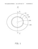
[0007]FIG. 1 is a perspective view of one embodiment of an artificial eye.
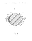
[0008]FIG. 2 is a cross-sectional view of the artificial eye of FIG. 1, taken alone line II-II.
[0009]FIG. 3 is a cross-sectional view of a pupil assembly of the artificial eye of FIG. 1.
[0010]FIG. 4 is a cross-sectional view of the pupil assembly, a pupil of the pupil assembly expanding.
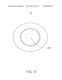
[0011]FIG. 5 is a perspective view of the artificial eye, the pupil expanding.
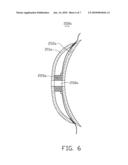
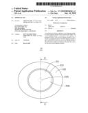
[0012]FIG. 6 is a cross-sectional view of one embodiment of a pupil assembly.
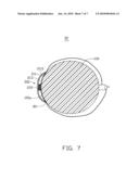
[0013]FIG. 7 is a cross-sectional view of another embodiment of an artificial eye.
DETAILED DESCRIPTION OF THE EMBODIMENTS
[0014]Referring to FIGS. 1 and 2, one embodiment of an artificial eye 10 includes a supporter 100 and a pupil assembly 200 positioned on the supporter 100.
[0015]The supporter 100 may be a substantially spherical-shaped body, and made of an elastic material. The supporter 100 has a surface 100a.
[0016]Also referring to FIG. 3, the pupil assembly 200 includes a first substantially circular-shaped clipping member 211, a second substantially circular-shaped clipping member 212, an electroactive pupil 220, a first electrode 231 and a second electrode 232. Each of the first and second clipping members 211, 212 may be a curved sheet. The first clipping member 211 has a concave surface 2110. The second clipping member 212 has a convex surface 2120. Peripheral portions of the first and second clipping members 211, 212 contact each other. In one embodiment, adhesive material members 80 are positioned between the peripheral portions to fix the first and second clipping members 211, 212 together. A gap 213 is defined between the concave surface 2110 and the convex surface 2120. The gap 213 may be a void space. The second clipping member 212 is positioned on the surface 100a. The first and second clipping members 211, 212 may be made of transparent materials, such as glass material, colored glass material, or polymethyl methacrylate (PMMA).
[0017]The electroactive pupil 220 is positioned in the gap 213 between the concave surface 2110 and the convex surface 2120, and made of an electroactive material, such as ion exchange membrane, gel polymer, electroactive polymer or piezoelectric polymer. The electroactive pupil 220 may be substantially cylindrical or spherical shaped. In the illustrated embodiment, the electroactive pupil 220 is substantially cylindrical shaped, has a first end 222 and a second end 224 opposite to the first end 222. The first end 222 contacts the concave surface 2110. The second end 224 contacts the convex surface 2120.
[0018]The first and second electrodes 231, 232 are positioned at two opposite ends of the electroactive pupil 220. The first electrode 231 is electrically coupled to a power source 70 via one conductive wire 90. The second electrode 232 is electrically coupled to a switch 60 via another conductive wire 90. The switch 60 is electrically coupled to the power source 70 and configured to turn on and turn off the power source 70. As a result, the electroactive pupil 220, the first and the second electrodes 231, 232, the power source 70 and the switch 60 constitute a circuit.
[0019]Also referring to FIGS. 4 and 5, in use, when the switch 60 is controlled to turn the power source 70 on, the electroactive pupil 220 is powered on to expand into the gap 213. When the switch 60 is controlled to turn the power source 70 off, the electroactive pupil 220 shrinks. Therefore, the artificial eye 10 can more realistically simulate a human eye.
[0020]Referring to FIG. 6, another embodiment of a pupil assembly 200a is similar to the pupil assembly 200 of FIG. 3, except that a through hole 250a is defined in the first clipping member 211a, the pupil 220a and the second clipping member 212a. The through hole 250a allows a digital camera to be positioned therein.
[0021]Referring to FIG. 7, another embodiment of an artificial eye 30 is similar to the artificial eye 10 of FIGS. 1 through 3, except that the electroactive pupil assembly 300 includes the clipping member 211 and the electroactive pupil 220. The gap 213 is defined between the concave surface 2110 of the clipping member 211 and the surface 100a. The electroactive pupil 220 is positioned between the concave surface 2110 and the surface 100a. The adhesive material members 80 are positioned between peripheral portion of the clipping member 211 and the surface 100a, thereby fixing the clipping member 211 to the supporter 100.
[0022]It is believed that the present embodiments and their advantages will be understood from the foregoing description, and it will be apparent that various changes may be made thereto without departing from the spirit and scope of the embodiments or sacrificing all of its material advantages.
User Contributions:
comments("1"); ?> comment_form("1"); ?>Inventors list |
Agents list |
Assignees list |
List by place |
Classification tree browser |
Top 100 Inventors |
Top 100 Agents |
Top 100 Assignees |
Usenet FAQ Index |
Documents |
Other FAQs |
User Contributions:
Comment about this patent or add new information about this topic:
| People who visited this patent also read: | |
| Patent application number | Title |
|---|---|
| 20120148572 | NOVEL ANTIBODIES |
| 20120148571 | AMINO ACID SEQUENCES THAT BIND TO SERUM PROTEINS IN A MANNER THAT IS ESSENTIALLY INDEPENDENT OF THE PH, COMPOUNDS COMPRISING THE SAME, AND USES THEREOF |
| 20120148570 | METHODS AND COMPOSITIONS FOR TREATING RESPIRATORY DISEASE-CHALLENGED ANIMALS |
| 20120148569 | PICRORHIZA KURROA EXTRACT FOR PREVENTION, ELIMINATION AND TREATMENT OF INFECTION DISEASES |
| 20120148568 | Variant Immunoglobulins with Improved Manufacturability |
Images included with this patent application:
 |  |
 |  |
 |  |
 |  |
| Similar patent applications: | |
| Date | Title |
|---|---|
| 2008-09-11 | Artificial eye socket system and method |
| 2008-10-23 | Bio artificial eye and conformer |
| 2009-05-07 | Artificial heart pump system and its control apparatus |
| 2009-10-01 | Artificial sphincter system |
| 2011-06-30 | Artificial limb protection system |
| New patent applications in this class: | |
| Date | Title |
|---|---|
| 2015-12-03 | Ocular prosthesis with display device |
| 2015-11-12 | Artificial eyes and manufacture thereof |
| 2014-07-31 | Animatronic eye with an electromagnetic drive and fluid suspension and with video capability |
| 2013-11-28 | Artificial eyes and manufacture thereof |
| 2012-06-28 | Uveoscleral drug delivery implant and methods for implanting the same |
| New patent applications from these inventors: | |
| Date | Title |
|---|---|
| 2013-03-14 | Lens module |
| 2013-03-14 | Lens module having light-shielding plate |
| 2013-03-07 | Lens module with anti-reflection film |
| 2013-02-28 | Lens module |
| 2013-02-21 | Optical lens and image pick-up apparatus having same |
| Top Inventors for class "Prosthesis (i.e., artificial body members), parts thereof, or aids and accessories therefor" | |
| Rank | Inventor's name |
|---|---|
| 1 | Anton G. Clifford |
| 2 | Yunbing Wang |
| 3 | Jan Weber |
| 4 | Chad Glerum |
| 5 | Robert Metzger |