Patent application title: Utility cover having a bowl cavity and a removable lid
Inventors:
Michael A. Stetson (Lake Elsinore, CA, US)
IPC8 Class: AB65D5100FI
USPC Class:
220200
Class name: Receptacles closures
Publication date: 2009-12-31
Patent application number: 20090321442
Inventors list |
Agents list |
Assignees list |
List by place |
Classification tree browser |
Top 100 Inventors |
Top 100 Agents |
Top 100 Assignees |
Usenet FAQ Index |
Documents |
Other FAQs |
Patent application title: Utility cover having a bowl cavity and a removable lid
Inventors:
Michael A. Stetson
Agents:
STETINA BRUNDA GARRED & BRUCKER
Assignees:
Origin: ALISO VIEJO, CA US
IPC8 Class: AB65D5100FI
USPC Class:
220200
Patent application number: 20090321442
Abstract:
There is provided a utility access opening cover. The cover includes a
bowl element having bowl upper and lower faces and a bowl wall disposed
about a bowl axis. The bowl wall extends between the bowl upper and lower
faces. The bowl wall defining a bowl cavity configured to receive a
filling material. A support sleeve is disposable within the utility
access opening. The support sleeve defines a sleeve axis and includes a
sleeve inner wall and sleeve upper and lower faces. The sleeve inner wall
extends between the sleeve upper and lower faces to define a sleeve
opening. The sleeve inner wall is sized and configured to engage with the
bowl wall with the bowl element being received within the support sleeve
opening to align the bowl axis with the sleeve axis. A lid is disposable
in contact with the bowl element to substantially cover the bowl cavity.Claims:
1. A cover for a utility access opening extending through a fabricated
layer having an exposed surface, the cover comprising:a bowl element
including a bowl upper face, a bowl lower face, and a bowl wall extending
between the bowl upper face and the bowl lower face, the bowl element
defining a bowl axis, the bowl wall being disposed about a bowl axis, the
bowl wall defining a bowl cavity configured to receive a filling
material;a support sleeve defining a sleeve axis, the support sleeve
having a sleeve inner wall, a sleeve upper face and a sleeve lower face,
the sleeve inner wall extending between the sleeve upper face and the
sleeve lower face to define a sleeve opening, the support sleeve being
disposable within the utility access opening, the sleeve inner wall being
sized and configured to engage with the bowl wall with the bowl element
being received within the support sleeve opening to align the bowl axis
with the sleeve axis; anda lid being disposable in contact with the bowl
element, the lid being sized to substantially cover the bowl cavity.
2. The cover as recited in claim 1 wherein the support sleeve includes a sleeve primary collar defining the sleeve upper face and a sleeve secondary collar defining the sleeve lower face.
3. The cover as recited in claim 2 wherein the sleeve primary collar defines a primary diameter and the sleeve secondary collar defines a secondary diameter being less than the primary diameter.
4. The cover as recited in claim 2 wherein the sleeve primary collar is circumscribable about the bowl wall when the bowl element is received within the support sleeve.
5. The cover as recited in claim 2 wherein the support sleeve further includes a support ledge extending between the sleeve primary collar and the sleeve secondary collar.
6. The cover as recited in claim 5 wherein the bowl element is disposable adjacent the support ledge.
7. The cover as recited in claim 1 further including a bowl gripping member connected to the bowl element for facilitating disengagement of the bowl element from the support sleeve.
8. The cover as recited in claim 7 wherein the lid includes a lid cutout extending through the lid upper surface, the lid being disposable on the bowl element to align the lid cutout with the bowl gripping member.
9. The cover as recited in claim 7 wherein the bowl gripping member defines a gripping member opening.
10. The cover as recited in claim 1 wherein the bowl element includes a support stud extending from the bowl lower face, the support stud being sized and configured to support the lid when the lid is disposed on the bowl element.
11. The cover as recited in claim 10 wherein the lid includes a lid contact surface being disposable in contact with the support stud.
12. The cover as recited in claim 10 further including a bowl gripping member connected to the bowl element for facilitating disengagement of the bowl element from the support sleeve.
13. The cover as recited in claim 12 wherein the lid includes a lid cutout extending through the lid upper surface, the lid being disposable on the bowl element to align the lid cutout with the bowl gripping member.
14. The cover as recited in claim 1 wherein the lid includes a lid upper surface being substantially flush with the exposed surface when the lid is disposed in contact with the bowl element.
15. The cover as recited in claim 1 wherein the lid includes a lid contact surface being disposable in contact with the bowl element.
16. A cover for a utility access opening extending through a fabricated layer having an exposed surface, the cover comprising:a bowl element including a bowl upper face, a bowl lower face, and a bowl wall extending between the bowl upper face and the bowl lower face, the bowl element defining a bowl axis, the bowl wall being disposed about a bowl axis;a support sleeve defining a sleeve axis, the support sleeve having a sleeve inner wall, a sleeve upper face and a sleeve lower face, the sleeve inner wall extending between the sleeve upper face and the sleeve lower face to define a sleeve opening, the support sleeve being disposable within the utility access opening, the sleeve inner wall being sized and configured to engage with the bowl wall with the bowl element being received within the support sleeve opening to align the bowl axis with the sleeve axis;a lid being disposable in contact with the bowl element, the lid being sized to substantially cover the bowl cavity; anda support stud extending from the bowl lower face, the support stud being sized and configured to support the lid when the lid is disposed on the bowl element.
17. The cover as recited in claim 16 wherein the lid includes a lid contact surface being disposable in contact with the support stud.
18. The cover as recited in claim 16 wherein the support sleeve includes a sleeve primary collar defining the sleeve upper face and a sleeve secondary collar defining the sleeve lower face.
19. The cover as recited in claim 18 wherein the sleeve primary collar defines a primary diameter and the sleeve secondary collar defines a secondary diameter being less than the primary diameter.
20. The cover as recited in claim 18 wherein the support sleeve further includes a support ledge extending between the sleeve primary collar and the sleeve secondary collar.
Description:
CROSS-REFERENCE TO RELATED APPLICATIONS
[0001]Not Applicable
STATEMENT RE: FEDERALLY SPONSORED RESEARCH/DEVELOPMENT
[0002]Not Applicable
BACKGROUND
[0003]1. Field of the Invention
[0004]The present invention relates generally to utility covers being disposable within a fabricated surface, and more specifically to a utility cover having a bowl cavity and a removable lid.
[0005]2. Description of the Prior Art
[0006]It is common for residential and commercial structures to include landscaping to enhance the structures' aesthetic appeal. The landscaping may include both softscape (e.g. flowers, plants, etc.) and hardscape (e.g. driveways, decks, pool areas, or the like). The hardscape portion of the landscape is typically formed of a fabricated material. Exemplary fabricated materials include concrete, tile, exposed aggregate, or brick. The hardscaping and softscaping portions collectively form the overall landscaping design which typically enhances the appearance of the property.
[0007]Landscaping designs commonly incorporate elements requiring utility connections. For example, the property may include a pool, spa, or other water feature requiring plumbing for normal operation. The landscape design may further include landscape lighting requiring electricity. Therefore, utility conduits are typically routed throughout the property to provide the utilities needed by the elements incorporated in the landscape design.
[0008]Routine maintenance and operation of one or more landscaping elements may require access to the utilities serving such elements. For instance, a pool typically includes a skimmer incorporated into the pool's plumbing system. As the water in the pool circulates through the plumbing system, the skimmer catches debris floating within the water. Therefore, after a period of time, the filter in the skimmer is generally removed to clean the debris from the filter.
[0009]Consequently, many landscape designs incorporate one or more utility access openings into the hardscaping portions of the overall landscape design to enable easy access to the utilities. With regard to the pool skimmer discussed above, a utility access opening is typically formed in the pool deck near the pool. Many pool decks are formed out of a concrete material which is poured around a frame to form the utility access opening.
[0010]A lid may be disposed over the opening to cover the opening when access to the utility is not required. Oftentimes, the lid is formed of a plastic material which tends to be aesthetically unpleasing and structurally deficient. In particular, the lids tend to be weak and prone to cracking, especially after prolonged exposure to the sun. Consequently, the lid may not be capable of supporting loads typically applied to the lid, such as the weight of someone walking over the lid. Therefore, the lid may create a safety hazard. The prior art covers tend to be formed of a weak, flimsy material which may not be strong enough to support the weight of someone walking over the lid. Furthermore, prolonged exposure to the sun tends to further weaken the lid.
[0011]As is apparent from the foregoing, there is a need in the art for an improved utility opening cover. The present invention addresses this particular need, as will be discussed in more detail below.
BRIEF SUMMARY
[0012]There is provided a cover for a utility access opening extending through a fabricated layer having an exposed surface. The cover includes a bowl element defining a bowl axis. The bowl element includes a bowl upper face, a bowl lower face, and a bowl wall disposed about the bowl axis. The bowl wall extends between the bowl upper face and the bowl lower face. The bowl wall defines a bowl cavity configured to receive a filling material. The cover further includes a support sleeve disposable within the utility access opening. The support sleeve defines a sleeve axis and includes a sleeve inner wall, a sleeve upper face and a sleeve lower face. The sleeve inner wall extends between the sleeve upper face and the sleeve lower face to define a sleeve opening. The sleeve inner wall is sized and configured to engage with the bowl wall with the bowl element being received within the support sleeve opening to align the bowl axis with the sleeve axis. The cover additionally includes a lid disposable in contact with the bowl element. The lid is sized to substantially cover the bowl cavity. The lid may include a lid upper surface that is substantially flush with the exposed surface when the lid is disposed in contact with the bowl element.
[0013]According to various aspects of the present invention, the cover may be employed to provide an aesthetically pleasing alternative to conventional utility covers. More specifically, a filling material may be disposed within the bowl cavity to enhance the appearance of the utility cover. For instance, the same material used to construct the fabricated surface may be used as the filling material. In this manner, the appearance of the utility cover may compliment the appearance of the fabricated layer. However, the lid may be disposed over the bowl cavity until the filling material is disposed therein. In this regard, the lid may provide a smoother transition between the fabricated layer and the cover until the bowl cavity is filled with the filling material.
[0014]If the bowl cavity is left uncovered, one ore more construction codes may be violated. Therefore, the lid may be placed over the bowl element to comply with such construction codes until the filling material is disposed within the bowl cavity. Furthermore, in some instance, it may be desirable to keep the lid disposed over the bowl element, rather than filling the bowl cavity with a filling material. Therefore, the lid provides the user with flexibility to fill the bowl cavity when desired.
[0015]The cover may include a support stud extending from the bowl lower face. The support stud may be sized and configured to support the lid when the lid is disposed on the bowl element. One or more support studs may extend from the bowl lower face to distribute the load applied to the lid, such as a person walking over the lid.
[0016]The present invention is best understood by reference to the following detailed description when read in conjunction with the accompanying drawings.
BRIEF DESCRIPTION OF THE DRAWINGS
[0017]These and other features and advantages of the various embodiments disclosed herein will be better understood with respect to the following description and drawings, in which like numbers refer to like parts throughout, and in which:
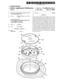
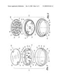
[0018]FIG. 1 is an exploded upper perspective view of a utility cover including a support sleeve, a bowl element and a lid;
[0019]FIG. 2 is an exploded lower perspective view of the utility cover illustrated in FIG. 1;
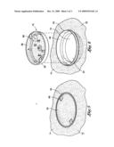
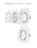
[0020]FIG. 3 is an upper perspective view of the utility cover illustrated in FIGS. 1-2, the utility cover being disposed within a utility access opening extending through a fabricated layer having an exposed surface;
[0021]FIG. 4 is an exploded upper perspective view of the utility cover illustrated in FIG. 3;
[0022]FIG. 5 is an upper perspective view of the utility cover, wherein the lid is removed and a filling material is disposed within the bowl element; and
[0023]FIG. 6 is an exploded upper perspective view of the utility cover illustrated in FIG. 5.
DETAILED DESCRIPTION
[0024]The detailed description set forth below in connection with the appended drawings is intended as a description of the presently preferred embodiment of the invention, and is not intended to represent the only form in which the present invention may be constructed or utilized. The description sets forth the functions of the invention in connection with the illustrated embodiment. It is to be understood, however, that the same or equivalent functions may be accomplished by different embodiments that are also intended to be encompassed within the scope of the invention. It is further understood that the use of relational terms such as first and second, top and bottom, and the like are used solely to distinguish one from another entity without necessarily requiring or implying any actual such relationship or order between such entities.
[0025]Referring now to the drawings wherein the showings are for purposes of illustrating a preferred embodiment of the present invention only, and not for purposes of limiting the same, FIGS. 1-6 illustrate a cover 10 constructed in accordance with an embodiment of the present invention. In particular, FIG. 1 is an exploded upper perspective view of the cover 10, while FIG. 2 is an exploded lower perspective view of the cover 10. The cover 10 is sized and configured to be disposed within a utility access opening 12 formed within a fabricated layer 14 defining an exposed surface 16. The exposed surface 16 is the exposed portion of the fabricated layer 14. In the case of a pool deck, the exposed surface 16 is the uppermost portion which a person walks on. The fabricated layer 14 may be formed from a wide range of materials, such as concrete, aggregate, stone, brick, or other materials commonly used in the art.
[0026]The utility access opening 12 may extend through the fabricated layer 14 to provide access to utilities such as plumbing, electricity, or pool equipment. For instance, the utility access opening 12 may provide access to a pool skimmer to allow for routine cleaning and maintenance thereof. The cover 10 may be disposed within the utility access opening 12 to cover the opening 12 when access is not required.
[0027]According to various aspects of the present invention, the cover 10 includes a support sleeve 40 that is disposable within the utility access opening 12. It is understood that the support sleeve 40 may not extend through the entire utility access opening 12. In other words, the support sleeve 40 may only partially extend through the opening 12. In some cases, the utility access opening 12 may be formed around the support sleeve 40. In this regard, the fabricated surface 14 is formed of a pourable material that is poured in the desired location and is allowed to cure or harden. In this instance, the fabricated surface 14 may be poured around the support sleeve 40 to define the utility access opening 12. However, it is also understood that the support sleeve 40 may be disposed within a preformed utility access opening 12.
[0028]The support sleeve 40 is disposed about a sleeve axis 46. In the particular embodiment shown in FIGS. 1-6, the support sleeve 40 is substantially circular; however, it is understood that the support sleeve 40 may define a non circular configuration. The support sleeve 40 includes a sleeve inner wall 48 extending between a sleeve upper face 50 and a sleeve lower face 52 to define a sleeve opening 54. The sleeve 40 also defines a sleeve outer wall 56 that is disposable in contact with the fabricated layer 14. The distance between the sleeve upper face 50 and the sleeve lower face 52 defines a sleeve height. In one embodiment, the sleeve height may be equal to the thickness of the fabricated layer 14. In this manner, the sleeve 40 may fully extend through the opening 12. In another embodiment, the thickness of the fabricated layer 14 is greater than the sleeve height. In this case, the sleeve 40 only partially extends through the fabricated layer 14.
[0029]In one embodiment, the support sleeve 40 defines a sleeve primary collar 42 and a sleeve secondary collar 44. The sleeve primary collar 42 defines a primary diameter and the sleeve secondary collar defines a secondary diameter that is less than the primary diameter. Therefore, a support ledge 58 extends between the sleeve primary collar 42 and the sleeve secondary collar 44. The support sleeve 40 is sized and configured to receive and support a bowl element 18 as depicted in FIGS. 1 and 2. According to one embodiment, the bowl element 18 may be placed on the support ledge 58 when the bowl element 18 is received by the support sleeve 40.
[0030]Although the foregoing describes a support sleeve 40 having a primary and secondary collar, it is understood that other embodiments of the support sleeve 40 may define other shapes and configurations. For instance, the support sleeve 40 may have an inner diameter that tapers inwardly from the sleeve upper face 50 toward the sleeve lower face 52. The bowl element 18 may have a complementary configuration which allows the bowl element 18 to be received and supported by the support sleeve 40.
[0031]The bowl element 18 is disposable within the sleeve opening 54 to substantially cover the same. The bowl element 18 includes a bowl wall 24 disposed about a bowl axis 32. The bowl wall 24 extends between a bowl upper face 20 and a bowl lower face 22. It may be desirable for the bowl element 18 to define a size and shape that is complimentary to the support sleeve 40 to facilitate engagement between the bowl element 18 and the support sleeve 40, as well as to sufficiently cover the utility access opening 12. In the embodiment shown in FIGS. 1-6, the bowl wall 24 is substantially circular in shape. However, it is understood that the bowl wall 24 may define other non circular shapes without departing from the spirit and scope of the present invention.
[0032]The bowl wall 24 defines a bowl cavity 30 configured to receive a filling material. The filling material may be the same material used to form the fabricated layer 14. In this manner, the appearance of the cover 10 may blend in with the appearance of the fabricated layer 14. Furthermore, when the selected material is identical to the material of the fabricated layer 14, the layer formed by the filling material and fabricated layer 14 will have compatible functional properties, such as respective coefficients of friction and coefficients of expansion. To this end, it may be desirable for the filling material to be identical to the material used to form the fabricated layer 14. While a homogenous material is shown in FIGS. 5-6, it is to be understood that non-homogenous materials, such as stone and mortar, tile and grout, or other materials known by the art can also be placed within the bowl cavity 30. For more information about disposing a filling material within the bowl cavity 30, please refer to U.S. Pat. No. 6,393,771 entitled Cover for Closing Surface Disposed Utility Access Opening, the contents of which are expressly incorporated herein by reference.
[0033]The bowl wall 24 defines a bowl wall inner face 28 and a bowl wall outer face 26. In the particular embodiment shown in FIGS. 1-6, the sleeve inner wall 48 is sized and configured to engage with the bowl wall outer face 26. In this manner, the bowl element 18 is received within the support sleeve opening 54 to align the bowl axis 32 with the sleeve axis 46. In other words, the bowl element 18 is coaxially disposed with the support sleeve 40 when the bowl element 18 is received within and engaged with the support sleeve 40.
[0034]The cover 10 further includes a lid 60 disposable in contact with the bowl element 18 to substantially cover the bowl cavity 30. In one embodiment, when the lid 60 is disposed in contact with the bowl element 18, a lid upper surface 62 is substantially flush with the exposed surface 16 of the fabricated layer 14 to provide a smooth transition between the exposed surface 16 and the lid upper surface 62. In this regard, it is not required that the lid upper surface 62 form a fluid-tight seal with the exposed surface 16. Rather, when the lid 60 is disposed in contact with the bowl element 18, the lid upper surface 62 and the exposed surface 16 of the fabricated layer 14 are disposed in a substantially co-planar arrangement.
[0035]Although the bowl cavity 30 is configured to receive a filling material, the lid 60 may be disposed in contact with the bowl element 18 to cover the bowl cavity 30 prior to disposal of the filling material therein. For instance, the filling material may not be available until after installation of the cover 10. Therefore, the lid 60 may be temporarily disposed over the bowl cavity 30 to cover the bowl cavity 30 until it is filled with the filling material. Furthermore, leaving the bowl cavity 30 unfilled or uncovered may violate certain construction codes. Therefore, the lid 60 may be disposed over the bowl cavity 30 to bring the cover 10 into compliance with such construction codes.
[0036]Moreover, in certain circumstances it may be desirable to leave the bowl cavity 30 unfilled. For instance, additional time and expense may be saved by foregoing disposal of the filling material within the bowl cavity 30. Therefore, the lid 60 may be placed over the bowl element 18 to cover the bowl cavity 30 on a more permanent basis. However, if at any point a user decides to fill the bowl cavity 30 with the filling material, the lid 60 may simply be removed from the bowl element 18 to allow the filling material to be disposed therein.
[0037]The lid 60 may include a plurality of lid ribs 76 extending from the lid upper surface 62. The lid ribs 76 collectively define a lid contact surface 74 that is disposable in contact with the bowl element 18 when the lid 60 is disposed over the bowl cavity 30. The bowl element 18 may include one or more support studs 72 for supporting the lid 60. In particular, the lid contact surface 74 may be disposed in contact with the support stud 72 when the lid 60 is disposed over the bowl cavity 30. The support studs 72 may be disposed in spaced relation to each other to distribute the load associated with supporting the lid 60. For instance, it is contemplated that the lid 60 may be required to support a load applied thereto, such as a person walking over the lid 60. Therefore, the support studs 72 distribute the load applied to the lid 60. In the particular embodiment depicted in FIG. 1, the bowl element 18 includes four support studs 72 near the center of the bowl element 18 and several support studs 72 near the periphery of the bowl element 18.
[0038]The lid 60 may include a lid collar 64 extending from the lid upper surface 62 adjacent to the periphery of the lid 60. The bowl wall inner face 28 may be circumscribable about the lid collar 64 when the lid 60 is disposable over the bowl cavity 30. In this manner, the lid collar 64 may be received within the bowl element 18 when the lid 60 is properly placed over the bowl element 18.
[0039]In order to access utilities within the utility access opening 12, the bowl element 18 may be removed from the support sleeve 40 to uncover the utility access opening 12. To this end, the bowl element 18 may include structural attributes configured to facilitate removal of the bowl element 18 from the sleeve 40. Likewise, the lid 60 may also include structural attributes configured to facilitate removal of the lid 60 from the bowl element 18.
[0040]With regard to the bowl element 18, one embodiment includes one or more bowl gripping members 66 configured to enable a user to lift the bowl element 18 from engagement with the support sleeve 40. As shown in FIG. 1, the bowl element 18 includes a pair of opposing bowl gripping members 66. Each bowl gripping member 66 defines a gripping member opening 68 through which a tool or a user's finger may be inserted to pull the bowl element 18 out of the utility access opening 12 to access utilities therein. As shown, the bowl gripping member 66 extends from the bowl upper face 20 to the bowl lower face 22. The bowl gripping members 66 depicted in FIG. 1 are disposed adjacent the bowl wall 24; however, it is understood that the bowl gripping members 66 may be disposed in spaced relation to the bowl wall 24.
[0041]The particular lid 60 depicted in FIG. 1 includes a pair of opposing lid cutouts 70 that are disposed about the bowl gripping member 66 when the lid 60 is disposed in contact with the bowl element 18. In this manner, the shape of the lid cutout 70 is complimentary to the shape of the bowl gripping member 66. The lid cutout 70 extends from the lid upper surface 62 to the lid contact surface 74.
[0042]Although the lid 60 may simply be placed over the bowl element 60, it may be desirable to secure the lid 60 thereto to mitigate unwanted removal of the lid 60 from the bowl element 18. Therefore, a fastener may be used to connect the bowl element 18 to the lid 60. The bowl element 18 and lid 60 may be configured to engagement via the fastener.
[0043]According to one embodiment, the bowl lower face 22 includes a bowl recess 78 defining a bowl recess opening 80. A fastener having a head portion and a shank portion may be disposed through the bowl recess opening 80 for engagement with the lid 60. The head portion of the fastener may define an outer diameter that is larger than the bowl recess opening 80 while the shank portion of the fastener may define a diameter that is less than the bowl recess opening 80 to enable passage therethrough.
[0044]The lid 60 may include a lid connection element 82 that is configured to engage with the fastener to secure the lid 60 to the bowl element 18. In one particular implementation, the lid connection element 82 may be internally threaded to engage with a screw; however other fasteners known by those skilled in the art may also be used to connect the bowl element 18 to the lid 60.
[0045]The above description is given by way of example, and not limitation. Given the above disclosure, one skilled in the art could devise variations that are within the scope and spirit of the invention disclosed herein. Further, the various features of the embodiments disclosed herein can be used alone, or in varying combinations with each other and are not intended to be limited to the specific combination described herein. Thus, the scope of the claims is not to be limited by the illustrated embodiments.
User Contributions:
comments("1"); ?> comment_form("1"); ?>Inventors list |
Agents list |
Assignees list |
List by place |
Classification tree browser |
Top 100 Inventors |
Top 100 Agents |
Top 100 Assignees |
Usenet FAQ Index |
Documents |
Other FAQs |
User Contributions:
Comment about this patent or add new information about this topic:
Images included with this patent application:
 |  |
 |  |
| New patent applications in this class: | |
| Date | Title |
|---|---|
| 2018-01-25 | Fluid housing of a fluid treatment system and fluid treatment system |
| 2016-06-23 | Bowl-shaped container |
| 2016-06-16 | Sealable packaging device and related method |
| 2016-05-12 | Disposable portable food container device |
| 2016-03-10 | Manufacturing method for plug for hole created in plate and plug for hole created in plate |
| New patent applications from these inventors: | |
| Date | Title |
|---|---|
| 2013-03-14 | Shower drain cover |
| 2012-03-08 | Fountain autofill valve kit |
| 2010-07-15 | Window bird house |
| 2008-11-06 | Deck drain cover |
| Top Inventors for class "Receptacles" | |
| Rank | Inventor's name |
|---|---|
| 1 | Daniel Lee Bizzell |
| 2 | Frank Yang |
| 3 | Terry Vovan |
| 4 | William P. Apps |
| 5 | Lowell L. Wood, Jr. |