Patent application title: Storage rack
Inventors:
Yu-Teng Lin (Taya Hsiang, TW)
IPC8 Class: AA47F514FI
USPC Class:
2111811
Class name: Supports: racks of wire
Publication date: 2009-12-17
Patent application number: 20090308825
Inventors list |
Agents list |
Assignees list |
List by place |
Classification tree browser |
Top 100 Inventors |
Top 100 Agents |
Top 100 Assignees |
Usenet FAQ Index |
Documents |
Other FAQs |
Patent application title: Storage rack
Inventors:
Yu-Teng Lin
Agents:
ROSENBERG, KLEIN & LEE
Assignees:
Origin: ELLICOTT CITY, MD US
IPC8 Class: AA47F514FI
USPC Class:
2111811
Patent application number: 20090308825
Abstract:
A storage rack a base frame rod structure formed by bending one single
metal wire rod into a predetermined shape and a top frame rod structure
formed by bending one single metal wire rod into a predetermined shape
and welded to the base frame rod structure such that multiple storage
racks can be received together by inserting one storage rack of another
storage rack to save storage space, or multiple storage racks can be
stacked together, constituting a multi-deck combination storage rack.Claims:
1. A storage rack comprising a base frame rod structure, said base frame
rod structure comprising two symmetrical pairs of foot rod portions, two
horizontal top rod portions transversely arranged in parallel at two
first opposite sides and respectively connected between top ends of said
foot rod portions, and two stretcher rod portions longitudinally arranged
in parallel at two second opposite sides perpendicular to said first
opposite sides and respectively connected between bottom ends of said
foot rod portions, the two foot rod portions of one same pair being kept
in a sloping status such that the distance between the two ends of the
two foot rod portions is smaller than the distance between the bottom
ends thereof; and a top frame rod structure, said top frame rod structure
comprising two longitudinal rod portions respectively spaced above said
stretcher rod portions in a parallel member, two transverse rod portions
respectively connected between and formed integral with two opposite ends
of said two longitudinal rod portions and respectively welded to the foot
rod portions of said base frame rod structure at an elevation below said
horizontal top rod portions, said longitudinal rod portions being
disposed at an elevation above said transverse rod portions so that a gap
is defined between said top frame rod structure and each said foot rod
portion in each of four corners of the storage rack.
2. The storage rack as claimed in claim 1, further comprising two supplementary bearing rods fixedly connected between said two horizontal top rod portions and arranged in parallel, each said supplementary bearing rod having a longitudinal series of wave-like portions.
3. The storage rack as claimed in claim 1, as claimed in claim 1, wherein said stretcher rod portions being disposed at an elevation above the bottom ends of said foot rod portions so that each stretcher rod portion has each end thereof terminating in a downwardly curved protruding portion that connects to the bottom end of one said foot rod portion
Description:
BACKGROUND OF THE INVENTION
[0001]1. Field of the Invention
[0002]The present invention relates to racks and more particularly, to a storage rack that allows multiple storage racks to be received together, saving storage space.
[0003]2. Description of the Related Art
[0004]A typical bottle rack is made by means of fastening metal wire rods and/or metal frame members together subject to the desired shape by means of welding. A bottle rack of this type is not collapsible. There is known a detachable bottle rack made by means of fastening metal wire rods and/or metal frame members together with screws subject to the desired shape. When mounting or dismounting this design of bottle rack, a screwdriver must be used.
SUMMARY OF THE INVENTION
[0005]It is one object of the present invention to provide a storage rack, which allows multiple storage racks to be received together by inserting one storage rack of another storage rack to save storage space. It is another object of the present invention to provide a storage rack, which allows multiple storage racks to be stacked together, constituting a multi-deck combination storage rack.
[0006]To achieve these and other objects of the present invention, the storage rack comprises a base frame rod structure and a top frame rod structure. The base frame rod structure comprises two symmetrical pairs of foot rod portions, two horizontal top rod portions transversely arranged in parallel at two first opposite sides and respectively connected between top ends of the foot rod portions, and two stretcher rod portions longitudinally arranged in parallel at two second opposite sides perpendicular to the first opposite sides and respectively connected between bottom ends of the foot rod portions. The two foot rod portions of one same pair are kept in a sloping status such that the distance between the two ends of the two foot rod portions is smaller than the distance between the bottom ends thereof. The top frame rod structure comprises two longitudinal rod portions respectively spaced above the stretcher rod portions in a parallel member, two transverse rod portions respectively connected between and formed integral with two opposite ends of the two longitudinal rod portions and respectively welded to the foot rod portions of the base frame rod structure at an elevation below the horizontal top rod portions. The longitudinal rod portions are disposed at an elevation above the transverse rod portions so that a gap is defined between the top frame rod structure and each foot rod portion in each of the four corners of the storage rack.
BRIEF DESCRIPTION OF THE DRAWINGS
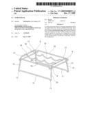
[0007]FIG. 1 is an elevational view of a storage rack in accordance with a first embodiment of the present invention.
[0008]FIG. 2 is a schematic drawing showing multiple storage racks of the first embodiment of the present invention received together.
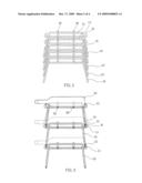
[0009]FIG. 3 is a schematic drawing showing a multi-deck combination storage rack formed of multiple storage racks of the first embodiment of the present invention.
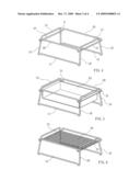
[0010]FIG. 4 is an elevational view of a storage rack in accordance with a second embodiment of the present invention.
[0011]FIG. 5 corresponds to FIG. 4, showing a storage box fastened to the transverse rod portions of the storage rack.
[0012]FIG. 6 corresponds to FIG. 4, showing a latticed sheet member fastened to the transverse rod portions of the storage rack.
[0013]FIG. 7 is an elevational view of a storage rack in accordance with a third embodiment of the present invention.
DETAILED DESCRIPTION OF THE PREFERRED EMBODIMENT
[0014]Referring to FIG. 1, a storage rack in accordance with a first embodiment of the present invention is shown comprised of a base frame rod structure and a top frame rod structure. The base frame rod structure comprises two symmetrical pairs of foot rod portions 10, two horizontal top rod portions 12 transversely arranged in parallel at two first opposite sides and respectively connected between the top ends of the foot rod portions 10, and two stretcher rod portions 11 longitudinally arranged in parallel at two second opposite sides perpendicular to the first opposite sides and respectively connected between the bottom ends of the foot rod portions 10. The stretcher rod portions 11 are disposed at an elevation slightly above the bottom ends of the foot rod portions 10 so that each stretcher rod portion 11 has each end terminating in a downwardly curved protruding portion 13 that connects to the bottom end of one foot rod portion 10. Further, the two foot rod portions 10 of one same pair slope are kept in a sloping status such that the distance between the two ends of the two foot rod portions 10 is smaller than the distance between the bottom ends thereof. The top frame rod structure comprises two longitudinal rod portions 20 respectively spaced above the stretcher rod portions 11 in a parallel member, two transverse rod portions 21 respectively connected between and formed integral with the two opposite ends of the two longitudinal rod portions 20 and respectively welded to the foot rod portions 10 of the base frame rod structure at an elevation below the horizontal top rod portions 12. The longitudinal rod portions 20 are disposed at an elevation slightly above the transverse rod portions 21 so that a gap H is defined between the top frame rod structure and each foot rod portion 10 in each of the four corners of the bottle rack. According to this design, the storage rack is a bottle rack.
[0015]Further, two supplementary bearing rods 30 are fixedly connected between the two horizontal top rod portions 12 and arranged in parallel, each having a longitudinal series of wave-like portions 31.
[0016]Referring to FIG. 2, multiple storage racks can be stacked together, saving storage space.
[0017]Referring to FIG. 3, the foot rod portions 10 of one storage rack can be forced inwards in transverse direction to have the stretcher rod portions 11 of the storage rack be engaged into the gaps H defined between the top frame rod structure and the foot rod portions 10 in the four corners of another storage rack. Therefore, multiple storage (bottle) racks can be arranged together, constituting a multi-deck combination storage rack. When multiple storage racks are arranged together to constitute a multi-deck combination storage rack, the downwardly curved protruding portions 13 of one upper storage rack are respectively clamped on the transverse rod portions 21 of one lower storage rack, enhancing the connection stability.
[0018]FIG. 4 shows a storage rack in accordance with a second embodiment of the present invention. This embodiment eliminates the aforesaid supplementary bearing rods 30. Further, a storage box 33 (see FIG. 5) or latticed sheet member 34 can be fastened the transverse rod portions 21 for holding things.
[0019]FIG. 7 shows a storage rack in accordance with a third embodiment of the present invention. This embodiment is based on the design of the aforesaid second embodiment shown in FIG. 4 with the exception that the stretcher rod portions 110 and the transverse rod portions 210 are smoothly arched.
[0020]Although a particular embodiment of the invention has been described in detail for purposes of illustration, various modifications and enhancements may be made without departing from the spirit and scope of the invention. Accordingly, the invention is not to be limited except as by the appended claims.
User Contributions:
comments("1"); ?> comment_form("1"); ?>Inventors list |
Agents list |
Assignees list |
List by place |
Classification tree browser |
Top 100 Inventors |
Top 100 Agents |
Top 100 Assignees |
Usenet FAQ Index |
Documents |
Other FAQs |
User Contributions:
Comment about this patent or add new information about this topic:
Images included with this patent application:
 |  |
 |  |
 |
| New patent applications in this class: | |
| Date | Title |
|---|---|
| 2013-11-21 | Rack system |
| 2013-10-03 | Recording device cage and method of use |
| 2013-07-04 | Container for the positionally oriented supply of tools... |
| 2013-07-04 | Decorative apparatus to hold candy |
| 2010-09-02 | Adjustable partition for bottom mount freezer |
| Top Inventors for class "Supports: racks" | |
| Rank | Inventor's name |
|---|---|
| 1 | Stephen N. Hardy |
| 2 | Wen-Tsan Wang |
| 3 | Gregory M. Bird |
| 4 | Shane Obitts |
| 5 | Kaveh Didehvar |