Patent application title: Emergency Stop System for a Group of Machine Units
Inventors:
Jan-Erik Ronny Olsson (Vrigstad, SE)
Nils Peter Wilhelm Berg (Bjorkoby, SE)
IPC8 Class: AF16P300FI
USPC Class:
1921165
Class name: Clutches and power-stop control stop mechanism
Publication date: 2009-12-17
Patent application number: 20090308708
Inventors list |
Agents list |
Assignees list |
List by place |
Classification tree browser |
Top 100 Inventors |
Top 100 Agents |
Top 100 Assignees |
Usenet FAQ Index |
Documents |
Other FAQs |
Patent application title: Emergency Stop System for a Group of Machine Units
Inventors:
Jan-Erik Ronny Olsson
Nils Peter Wilhelm Berg
Agents:
Jan-Erik Olson
Assignees:
Origin: VRIGSTAD, SE
IPC8 Class: AF16P300FI
USPC Class:
1921165
Patent application number: 20090308708
Abstract:
An emergency stop system for a group of machine units (1), driven by
energy from a source (2) is disclosed. The machine units are provided
with a cut off means (3) for the energy feed, that can be acted upon via
a receiver (5) by a transmitted signal, with a radio frequency, from a
transmitter in a group of mobile units (7), provided with such, carried
by one or several operators. Primarily the emergency stop systems is
characterised in that every machine unit (1) is provided with a
communication unit (4) in the form of a transmitter/receiver (5) for
radio- resp. IR-frequency in contact with a computer unit (6). Each
mobile unit (7) is provided with a transmitter/receiver for radio- resp.
IR-frequency for identifying and authorizing communication. The cut off
means (3) is provided not to be activated or inactivated without
foregoing identifying and authorizing IR-communication.Claims:
1. An emergency stop system for a group of machine units (1), driven by
energy from a source (2) such as an electrical net, medium under pressure
etc, whereas each of the machine units is provided with a cut off means
(3) for the energy feed, acted upon via a receiver (5) by a transmitted
signal, with a radio frequency, from a transmitter in a group of mobile
units (7), provided with such, carried by one or several
operatorscharacterised in thatevery machine unit (1) is provided with a
communication unit (4) comprising an transmitter/receiver (5) for radio-
resp. IR-frequency in contact with a computer unit (6) and each mobile
unit (7) is provided with a transmitter/receiver for radio- resp-
IR-frequency for identifying and authorizing communication, whereas the
cutoff means (3) is provided not to be activated or inactivated without
foregoing identifying and authorizing IR-communication
2. An emergency atop system according to claim 1,characterised in thatthe communicating unit (4) is provided to continually warrant the radio communication with the identifying and authorizing mobile unit, whereas it is provided to emit alarm (12), preferably optically or acoustically when the communication is interrupted.
3. An emergency stop system according to claim 1 or 2,characterized in thatthe mobile unit (7) is provided with a display, arranged to show the status for the communication with the communication unit (4),
4. An emergency stop according to any of the preceding claims,characterised in thatit comprises one sole machine unit.
Description:
[0001]The present invention relates to an emergency stop system tor a
group of machine units, driven by energy from a source such as an
electrical net, medium under pressure etc, whereas each of the machine
units is provided with a cut off means for the energy feed, acted upon
via a receiver by a transmitted signal, with a radio frequency, from a
transmitter in a group of mobile units, provided with such, carried by
one or several operators. [0002]The invention also relates to an
emergency stop system for one machine unit.
[0003]Such emergency stop systems are known since a long time e g from GB 2 198 614 A. In this publication there is disclosed an emergency stop system comprising a cut off means in the form of a primary control element, provided for instance to open a circuit breaker in the energy feed to a machine or to close a valve as a response to a remotely transmitted radio-, sound- or ultrasound signal. Each operator carries a transmitter for transmitting this signal, such that the operator continuously is ready to cut off the energy feed in case of a threatening situation or accident. There ere further suggestions for designing emergency stop systems, especially for designing said transmitter. Emergency stop systems hitherto known lack authority identification and authorization. This means, that the machines may be started even if no mobile units are in operation. [0004]The object of the present invention is thus to create an emergency stop system of the art mentioned introductorily, admitting safe identifying and authorization of operators. [0005]Firstly such one is characterized in that every machine unit is provided with a communication unit comprising an IR-transmitter/receiver in contact with a computer unit and each mobile unit is provided with an IR-transmitter/receiver for identifying and authorizing communication, whereas the cut all means is provided not to be activated or inactivated without foregoing identifying and authorizing IR-communication.
[0006]In one preferred embodiment the communication is arranged to continually warrant the radio communication with the identified and authorized mobile unit, whereas it is provided to emit alarm, preferably optically or acoustically when the communication is interrupted. [0007]In one suitable embodiment, the the mobile unit is provided with a display, arranged to show the status for the communication with the communication unit.
[0008]In the following, the invention shall be described more in detail, reference being made to the enclosed schematic figures of which:
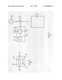
[0009]FIG. 1 shows a machine unit, connected to a source of energy, with a communication unit, whilst
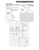
[0010]FIG. 2 shows a mobile unit.
[0011]In FIG. 1 a machine unit is marked by 1, a source of energy connected to it, by 2. The feed of energy to the machine unit may be cut off by a cut off means 3. A communication unit 4 is provided connected to the machine unit. It comprises a transmitter/receiver 5 for radio- resp. IR-frequency connected to a computer unit 6. In FIG. 2 there is shown a mobile unit 7, also provided with transmitter/receiver for radio- resp. IR-frequency. Radio frequency in this context for example moans 433.32 MHz, whilst IR-frequency means infrared light of a frequency, that is achieved by conventional devices. The mobile unit 7 is provided with a display 8, showing the status for the communication at radio frequency between the communication unit 4 and the mobile unit 7. This is equipped with a number of push buttons 9 for the communication with the communication unit and two buttons 10,11 for mutual emitting a signal for cutting off by the cutting off means 3. The computer unit 6 is also connected to an alarm 12, the function of which shall be described below. [0012]The requisite for starting a machine unit is that at least one operator has performed a coupling, this is to say, has established a radio contact with the machine unit in question. This is achieved in that the operator places himself relatively close to the machine unit in question and emits an IR-signal by pushing a button 9 at the mobile unit 7. Then the communication unit releases a signal to the mobile unit asking for the identity of same. Identity in this context means the personal data of one or several operators. Hereby the identity of one or several operators may be identified and authorized for the communication with one machine unit. At the display of the mobile unit the status of the communication may be read. [0013]Control of the communication can be performed continually between a coupled mobile unit and a communication unit. If the communication should be broken the computer unit 6 will release an alarm to the alarm unit 12, which alarm may he optical and/or acoustical.
User Contributions:
comments("1"); ?> comment_form("1"); ?>Inventors list |
Agents list |
Assignees list |
List by place |
Classification tree browser |
Top 100 Inventors |
Top 100 Agents |
Top 100 Assignees |
Usenet FAQ Index |
Documents |
Other FAQs |
User Contributions:
Comment about this patent or add new information about this topic:
| People who visited this patent also read: | |
| Patent application number | Title |
|---|---|
| 20220077207 | SOLID-STATE IMAGING DEVICE AND ELECTRONIC APPARATUS |
| 20220077206 | CMOS IMAGE SENSOR HAVING INDENTED PHOTODIODE STRUCTURE |
| 20220077205 | IMAGING DEVICE |
| 20220077204 | IMAGE SENSOR AND METHOD OF FABRICATING THE SAME |
| 20220077203 | IMAGING ELEMENT, FABRICATION METHOD, AND ELECTRONIC EQUIPMENT |
Images included with this patent application:
 |  |
| Similar patent applications: | |
| Date | Title |
|---|---|
| 2009-02-05 | Brake structure for a main shaft of a direct drive torque motor |
| 2009-11-12 | Stall detection system for mower blade clutch engagement |
| 2010-11-18 | Emergency unlocking device for a parking lock |
| 2011-09-29 | Oil passage structure for hydraulic clutch of an engine |
| 2011-09-29 | Oil passage structure for hydraulic clutch of an engine |
| Top Inventors for class "Clutches and power-stop control" | |
| Rank | Inventor's name |
|---|---|
| 1 | Farzad Samie |
| 2 | Stephan Maienschein |
| 3 | Chunhao J. Lee |
| 4 | Steven P. Moorman |
| 5 | Bret M. Olson |