Patent application title: Rectractable leash support
Inventors:
Steven T. Stuerke (Columbia, MO, US)
IPC8 Class: AA01K104FI
USPC Class:
119780
Class name: Animal controlling or handling (e.g., restraining, breaking, training, sorting, conveying, etc.) hitching or tethering rotary arm hitching device
Publication date: 2009-12-10
Patent application number: 20090301403
Inventors list |
Agents list |
Assignees list |
List by place |
Classification tree browser |
Top 100 Inventors |
Top 100 Agents |
Top 100 Assignees |
Usenet FAQ Index |
Documents |
Other FAQs |
Patent application title: Rectractable leash support
Inventors:
Steven T. Stuerke
Agents:
LITMAN LAW OFFICES, LTD.
Assignees:
Origin: ARLINGTON, VA US
IPC8 Class: AA01K104FI
USPC Class:
119780
Patent application number: 20090301403
Abstract:
The retractable leash support includes a bracket mounted on a rotatable
platform the rotatable platform being mountable to any fixed structure.
The bracket has two extension tubes spaced for receiving the grip portion
of a typical retractable pet leash, the extension tubes also being
adapted to accommodate a plate having complementary tubes that fit over
the extension tubes to secure the pet leash between the bracket and
plate. The extension tubes and complementary tubes of the plate have
holes that can be aligned. Pins are inserted into the aligned holes to
lock the pet leash grip securely in the leash support.Claims:
1. A retractable leash support, comprising:a rotatable platform adapted
for mounting on a supporting structure;a bracket mounted on the rotatable
platform;extension tubes extending from the bracket, the extension tubes
being spaced apart and adapted for receiving a grip portion of a typical
retractable pet leash;a plate;complementary tubes extending from the
plate, the complementary tubes telescoping over the extension tubes to
secure the pet leash between the bracket and the plate;alignment holes
disposed in the extension tubes and complementary tubes; andpins
insertable into the alignment holes to lock the pet leash grip securely
in the leash support.
2. The retractable leash support according to claim 1, further comprising:a stationary disk;a rotating disk attached in axial alignment with the stationary disk, the platform being attached to the rotating disk; andbearings disposed between the stationary disk and the rotating disk.
3. The retractable leash support according to claim 1, further comprising a pole, said rotatable platform being mounted on the pole.
4. The retractable leash support according to claim 1, wherein the Retractable leash support is mountable to a beam.
Description:
CROSS-REFERENCE TO RELATED APPLICATION
[0001]This application claims the benefit of U.S. Provisional Patent Application Ser. No. 61/129,156, filed Jun. 6, 2008.
BACKGROUND OF THE INVENTION
[0002]1. Field of the Invention
[0003]The present invention relates to animal tethers and more specifically to rotating animal tethers.
[0004]2. Description of the Related Art
[0005]On many occasions, a pet owner may wish to secure his/her pet with a tether in a designated location. The tether should provide a quality, worry free, non-tangling method of restraining the dog. Moreover the tether should not become an eyesore, regardless of where it is deployed. Preferably, the device should have the capability of rotating 360° when attached to a pole, which is in an open area.
[0006]There should preferably be a 32-foot radius for the pet to roam. The device should not drag chain on the landscape where the device is deployed, and should not have to be removed when an owner is mowing lawn or doing other landscape maintenance in the deployment area.
[0007]Thus a retractable leash support solving the aforementioned problems is desired.
SUMMARY OF THE INVENTION
[0008]The retractable leash support includes a bracket mounted on a rotatable platform the rotatable platform being mountable to any fixed structure. The bracket has two extension tubes spaced for receiving the grip portion of a typical retractable pet leash, the extension tubes also being adapted to accommodate a plate having complementary tubes that fit over the extension tubes to secure the pet leash between the bracket and plate. The extension tubes and complementary tubes of the plate have holes that can be aligned. Pins are inserted into the aligned holes to lock the pet leash grip securely in the leash support.
[0009]These and other features of the present invention will become readily apparent upon further review of the following specification and drawings.
BRIEF DESCRIPTION OF THE DRAWINGS
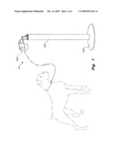
[0010]FIG. 1 is an environmental, perspective view of a retractable leash support according to the present invention.
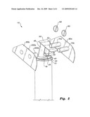
[0011]FIG. 2 is a partially exploded, perspective view of the retractable leash support according to the present invention.
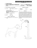
[0012]FIG. 3 is a perspective view of the retractable leash support using a first mounting option according to the present invention.
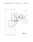
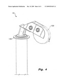
[0013]FIG. 4 is a perspective view of the retractable leash support using a second mounting option according to the present invention.
[0014]Similar reference characters denote corresponding features consistently throughout the attached drawings.
DETAILED DESCRIPTION OF THE PREFERRED EMBODIMENTS
[0015]As shown in FIGS. 1-4, the retractable leash support 10 includes a pet leash bracket 50 mounted on a rotatable platform, the rotatable platform being mountable to any fixed structure. The rotatable platform is comprised of a rotating disk 20 attached to a stationary disk 15 via an axial pin 30. Axial pin 30 may be disposed through a standoff nut 35 and washer 40. Ball bearings 18 are disposed between the stationary disk 15 and the rotating disk 20 to facilitate ease of rotation in the rotating disk 20. A grease fitting 25 may be disposed on rotating disk 20 to facilitate lubrication of the bearings 18.
[0016]As most clearly shown in FIGS. 1 and 4, the stationary disk 15 of the rotatable platform can be mounted to a flange 130 of a pole 120, the pole having a sturdy base 125. Alternatively, as shown in FIG. 3, the stationary disk 15 of the rotatable platform can be mounted to an auxiliary bracket 300, the auxiliary bracket 300 being affixed to, e.g., a post or beam. Mounting is not restricted to a post or beam, and the option to mount on various structure types depends only on the design choice of, e.g., auxiliary bracket 300 and the requirement that auxiliary bracket 300 have mounting hardware allowing the stationary disk 15 of the rotatable platform to be secured to the auxiliary bracket 300. For example, auxiliary bracket 300 could be adapted to mount retractable leash support 10 to a hitch ball of a recreational vehicle or, as shown in FIG. 3, auxiliary bracket 300 could be mounted to a post (the post being part of another structure, such as an outside deck, privacy fence, or the like).
[0017]Slightly angled, downward-projecting parallel attachment struts 45 extend from pet leash bracket 50 and are fastened to, welded, or otherwise affixed to the rotating disk 20. Vertical planar member 80a extends upward from the pet leash bracket 50 and may be unitarily constructed with the bracket 50 or may be a separate piece secured to the bracket 50 via a weld 55. Two extension tubes 70a and 70b extend horizontally from planar member 80a and are spaced for receiving the grip portion of a typical retractable pet leash 100, the extension tubes 70a and 70b also being adapted to accommodate a plate 80b having complementary tubes 200a and 200b that fit over the extension tubes 70a and 70b to secure the pet leash 100 between planar member 80a of the pet leash bracket 50 and plate 80b. The extension tubes 70a and 70b and complementary tubes 200a and 200b have holes that can be aligned. Pins 60 are inserted into the aligned holes to lock the pet leash grip securely in the leash support 10.
[0018]It is to be understood that the present invention is not limited to the embodiment described above, but encompasses any and all embodiments within the scope of the following claims.
User Contributions:
comments("1"); ?> comment_form("1"); ?>Inventors list |
Agents list |
Assignees list |
List by place |
Classification tree browser |
Top 100 Inventors |
Top 100 Agents |
Top 100 Assignees |
Usenet FAQ Index |
Documents |
Other FAQs |
User Contributions:
Comment about this patent or add new information about this topic:
| People who visited this patent also read: | |
| Patent application number | Title |
|---|---|
| 20100202402 | System And Method For Non-Contention Based Handover Based On Pre-Reserved Target Cell Uplink Allocations In Communication Systems |
| 20100202401 | METHOD AND APPARATUS OF HYBRID BURST MAPPING IN OFDMA SYSTEMS |
| 20100202400 | TRANSMISSION WITH COLLISION DETECTION AND MITIGATION FOR WIRELESS COMMUNICATION |
| 20100202399 | METHOD AND APPARATUS FOR PROCESSING TRANSMIT POWER CONTROL (TPC) COMMANDS IN A WIDEBAND CDMA (WCDMA) NETWORK BASED ON A SIGN METRIC |
| 20100202398 | SYSTEM FOR EFFICIENT RECOVERY OF NODE-B BUFFERED DATA FOLLOWING MAC LAYER RESET |
Images included with this patent application:
 |  |
 |  |
 |
| Similar patent applications: | |
| Date | Title |
|---|---|
| 2011-07-21 | Retractable leash and restraint assembly |
| 2009-05-14 | Retractable leash safety strap |
| 2010-02-18 | Transportable retractable leash |
| 2010-05-06 | Gentle stop retractable leash |
| 2010-08-26 | Retractable flat belt reflective pet leash |
| New patent applications in this class: | |
| Date | Title |
|---|---|
| 2010-09-09 | Tethering stake |
| Top Inventors for class "Animal husbandry" | |
| Rank | Inventor's name |
|---|---|
| 1 | Henk Hofman |
| 2 | Peter Willem Van Der Sluis |
| 3 | John M. Lipscomb |
| 4 | Karel Van Den Berg |
| 5 | Ype Groensma |