Patent application title: Water Deflector and System Having Multiple Water Deflectors of this Type
Inventors:
Carsten Paul (Garstedt, DE)
Assignees:
AIRBUS DEUTSCHLAND GMBH
IPC8 Class: AE06B726FI
USPC Class:
494761
Class name: Movable or removable closures closure seal; e.g., striker gasket or weatherstrip with fluid drain, or closure face mounted deflector; e.g., sill seal
Publication date: 2009-12-10
Patent application number: 20090300991
Inventors list |
Agents list |
Assignees list |
List by place |
Classification tree browser |
Top 100 Inventors |
Top 100 Agents |
Top 100 Assignees |
Usenet FAQ Index |
Documents |
Other FAQs |
Patent application title: Water Deflector and System Having Multiple Water Deflectors of this Type
Inventors:
Carsten Paul
Agents:
LERNER, DAVID, LITTENBERG,;KRUMHOLZ & MENTLIK
Assignees:
Airbus Deutschland GmbH
Origin: WESTFIELD, NJ US
IPC8 Class: AE06B726FI
USPC Class:
494761
Patent application number: 20090300991
Abstract:
A water deflector includes a water-diverting area and an attachment area
for attachment to a seal profile. The water-diverting area and the
attachment area are connected to one another via a connection area, which
is elastically deformable in such a way that when force acts on the
water-diverting area, it is movable in relation to the attachment area.
The water deflector can be used in the area of a door, wherein the water
deflector deforms when the door is closed and comes to rest in a cavity
between the seal profile and the door outer skin, and assumes its
starting shape again when the door is opened.Claims:
1. A water deflector comprising:a water-diverting area, and an attachment
area for attachment to a seal profile,wherein the water-diverting area
and the attachment area are connected to one another via a connection
area, which is elastically deformable such that when force acts on the
water-diverting area, it is movable in relation to the attachment area,
andwherein the water deflector has an essentially S-shaped
cross-sectional profile.
2. The water deflector of claim 1, wherein the water deflector comprises one piece having a pre-shaped rubber profile.
3. The water deflector of claim 1, wherein the attachment area is attachable to the seal profile via a holding plate using a screw and a rivet nut or a rivet.
4. (canceled)
5. The water deflector of claim 1, wherein the water deflector is positionable in the area of a door and deforms when the door is closed and comes to rest in a cavity between the seal profile and the door outer skin, and assumes its starting shape again when the door is opened.
6. The water deflector of claim 5, wherein the water-diverting area of the water deflector projects out beyond an outer planking when the door is open.
7. The water deflector of claim 5, wherein the outer planking is part of an aircraft.
8. A system comprising a plurality of water deflectors each comprising a water-diverting area, and an attachment area for attachment to a seal profile,wherein the water-diverting area, and the attachment area are connected to one another via a connection area, which is elastically deformable such that when force acts on the water-diverting area, it is movable in relation to the attachment area, andwherein the water deflector has an essentially S-shaped cross-sectional profile,said system further comprising a first water deflector having a linear rubber profile, on one end of which a second water deflector and on the other end of which a third water deflector are situated, each of which has a round rubber profile which corresponds to the contour of door cutout radii of the door.
9. The system of claim 8, wherein the plurality of water deflectors are welded to one another at their transitions.
Description:
[0001]This application claims the benefit of the filing date of U.S.
Provisional Patent Application No. 60/720,639 filed Sep. 26, 2005 and of
German Patent Application No. 10 2005 045 969.2 filed Sep. 26, 2005, the
disclosures of which are hereby incorporated herein by reference.
FIELD OF THE INVENTION
[0002]The present invention relates to a water deflector and a system having multiple water deflectors of this type, and particularly a water deflector which is used as a rain gutter to be employed in the door area of aircraft.
BACKGROUND OF THE INVENTION
[0003]Especially in the door area of aircraft, the problem occurs that rain water which is still between the seal profile of the jetway (Fingersteig) and the outer skin of the aircraft drips downward when the door is open and may hit an aircraft passenger going through the door.
SUMMARY OF THE INVENTION
[0004]There may be a need to find a possibility, using which an aircraft passenger may leave the aircraft without water dripping on his head.
[0005]This need may be met by a water deflector and system according claims 1 and 7. Advantageous embodiments of the present invention are specified in the dependent claims.
[0006]According to an exemplary embodiment of the present invention, the water deflector comprises a water-diverting area and an attachment area for attachment to a seal profile. The water-diverting area and the attachment area are connected to one another via a connection area, at least the connection area being elastically deformable in such a way that when a force acts on the water-diverting area, it is movable in relation to the attachment area.
[0007]The water deflector according to an exemplary embodiment of the present invention is preferably implemented in one piece or integrally, from hard rubber or a similar material, for example. Preferably, a preformed rubber profile is taken and mounted on the existing, frame-side seal profile of the door seal as the water deflector.
[0008]According to another exemplary embodiment of the present invention, the attachment area of the water deflector (the rubber profile) is attached to the seal profile via a holding plate using a screw and a rivet nut or a riveted connection.
[0009]According to another exemplary embodiment of the present invention, the water deflector has an essentially S-shaped cross-sectional profile.
[0010]The principle according to an exemplary embodiment of the present invention may be based on the water deflector deforming and coming to rest in a cavity between the seal profile and the door outer skin when the door is closed and assuming its starting shape again when the door is opened, the water-diverting area of the water deflector projecting out beyond outer skin of the aircraft when the door is open.
[0011]A system according to an exemplary embodiment of the present invention contains multiple above-mentioned water deflectors, for example, a first water deflector having a linear rubber profile, and a second and a third water deflector each being situated on the ends of the linear rubber profile and having a round rubber profile, which has the contour of door cutout radii of a door. The linear and the round rubber profiles preferably have an S-shaped cross-section.
[0012]The individual water deflectors are welded to one another or connected suitably in another way at their transitions, for example, so that no water may penetrate at the transitions.
SHORT DESCRIPTIONS OF THE DRAWINGS
[0013]In the following, preferred exemplary embodiments of the present invention are described with reference to the attached drawing.
[0014]FIG. 1 shows a partial cross-sectional view of a mounted water deflector according to an exemplary embodiment of the present invention from the side; and
[0015]FIG. 2 shows a system having multiple water deflectors of FIG. 1 according to an exemplary embodiment of the present invention.
DETAILED DESCRIPTION OF AN EXEMPLARY EMBODIMENT
[0016]In the following, identical reference signs identify identical or corresponding components in the various views of the figures.
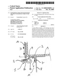
[0017]FIG. 1 shows a partial cross-sectional view which illustrates how a water deflector 1 according to an exemplary embodiment is mounted.
[0018]As shown in FIG. 1, the water deflector 1 contains a water-diverting or water-draining area 2, which is used as a rain or eaves gutter, an attachment area 3, and a connection area 4, which connects the water-diverting area 2 to the attachment area 3.
[0019]According to the exemplary embodiment, the water deflector 1 is implemented in one piece, for example, and comprises or consists of a hard rubber material or a similar material which allows elastic deformation of the water deflector.
[0020]At least the connection area 4 is elastically deformable in such a way that when a force acts on the water-diverting area 2, it is movable in the direction of the attachment area 3 and may be brought into a state B, as shown in FIG. 1. When a force no longer acts on the water-diverting area 2, the water deflector 1 assumes its original starting shape again (state A in FIG. 1).
[0021]As shown in FIG. 1, the attachment area 3 is attached to a seal profile 8 via a holding plate 5 using a screw 6 and a rivet nut 7. The seal profile 8 is a U-profile, for example, to one leg of which the attachment area 3 is attached. The seal profile 8 is attached to a longitudinal girder 9 using the other leg, for example, welded, riveted, etc.
[0022]According to an exemplary embodiment, an end of the holding plate or holding-down sheet 5 which points toward the longitudinal girder 9 is implemented as curved to ensure a secure contact of the attachment area 3 to the seal profile 8 and the longitudinal girder 9. The attachment area 3 of the water deflector 1 lies, in the mounted state, between the curved end of the holding plate 5 and the longitudinal girder 9 and between the essentially linear section of the holding plate 5 and the seal profile 8. The leg of the seal profile 8 to which the attachment area 3 of the water deflector 1 is attached extends essentially perpendicular to the leg of the longitudinal girder 9 which is attached to the other leg of the seal profile 8.
[0023]The longitudinal girder 9 is a U-profile, for example, on whose leg which is not attached to the seal profile 8, an outer planking 10 is fastened, the water-diverting area 2 projecting beyond the outer planking 10 in state A in such a way that water running down the outer planking 10 (indicated by the arrows D) runs down and is captured in the water-diverting area 2, as shown in FIG. 1.
[0024]When the door is closed (not shown), the water deflector 1 deforms in such a way that the water-diverting area 2 is brought from the state A into the state B and comes to rest in the cavity 11 between the seal profile 8 and the door outer skin (not shown). When the door is opened, the water deflector 1 assumes its starting shape again, the water-diverting area 2 returning from the state B back into the state A to capture and divert water D running down the outer planking 10, as explained in greater detail below with reference to FIG. 2.
[0025]FIG. 2 shows a system having multiple water deflectors of FIG. 1 according to a preferred exemplary embodiment of the present invention.
[0026]FIG. 2 shows a first water deflector 12 which has a linear profile. A second water deflector 13 and a third water deflector 14, each of which has a round profile which corresponds to the contour of the door cutout radii of a respective aircraft type, are located on the left and right of the first water deflector 12 in FIG. 2.
[0027]According to an exemplary embodiment, the first water deflector 12 is attached to a middle seal profile 15, as explained with reference to FIG. 1, and the second and third water deflectors 13, 14 are attached in a similar way to a left seal profile 16 and a right seal profile 17, respectively.
[0028]The three water deflectors 12, 13, 14 are welded to one another at transitions 18a, 18b.
[0029]Using the system shown in FIG. 2, residual rain water which still penetrates between the seal profile 15, 16, 17 and the outer planking may be captured and diverted to the side, where it flows downward in the profile of the door seal. An aircraft passenger may thus leave the aircraft without water dripping on his head.
[0030]Although the present invention was described above with reference to use in an aircraft, it is obvious that other areas of application in other vehicles are possible in which the same problem occurs.
[0031]It should be noted that the term "comprising" does not exclude other elements or steps and the "a" or "an" does not exclude a plurality. Also elements described in association with different embodiments may be combined. It should also be noted that reference signs in the claims shall not be construed as limiting the scope of the claims.
LIST OF REFERENCE SIGNS
[0032]1 water deflector
[0033]2 water-diverting area
[0034]3 attachment area
[0035]4 connection area
[0036]5 holding plate
[0037]6 screw
[0038]7 rivet nut (Anjatmutter)
[0039]8 seal profile
[0040]9 longitudinal girder
[0041]10 outer planking
[0042]11 cavity
[0043]12 first linear water deflector
[0044]13 second round water deflector
[0045]14 third round water deflector
[0046]15 middle seal profile
[0047]16 left seal profile
[0048]17 right seal profile
[0049]18a,b transitions
[0050]A starting state
[0051]B state upon force action
[0052]D water
User Contributions:
comments("1"); ?> comment_form("1"); ?>Inventors list |
Agents list |
Assignees list |
List by place |
Classification tree browser |
Top 100 Inventors |
Top 100 Agents |
Top 100 Assignees |
Usenet FAQ Index |
Documents |
Other FAQs |
User Contributions:
Comment about this patent or add new information about this topic:
Images included with this patent application:
 |  |
 |
| Similar patent applications: | |
| Date | Title |
|---|---|
| 2012-06-28 | Vehicle sash door and protector and center channel for the same |
| 2008-10-02 | Safety gate system having an electronic display |
| 2009-03-19 | Door hinge having a lifting function for the door |
| 2011-10-27 | Shipping container seal monitoring device, system and method |
| 2012-04-26 | Safety system, method, and electronic gate with the safety system |
| New patent applications in this class: | |
| Date | Title |
|---|---|
| 2016-07-14 | Weather strip |
| 2016-03-24 | Window pan drainage dam |
| 2014-06-26 | Gasket string, in particular for sealing a door jamb against a vehicle door |
| 2013-04-25 | Door weatherstrip |
| 2013-02-21 | Storm water entry prevention apparatus for sliding door system |
| New patent applications from these inventors: | |
| Date | Title |
|---|---|
| 2013-03-28 | Aircraft fuselage with door stoppers attached to a door frame bulkhead |
| 2012-10-18 | Equipment module for a vehicle and vehicle with a vehicle body comprising a cargo space |
| 2010-11-04 | Aircraft door and a method for the manufacture of an aircraft door of this type |
| 2010-10-07 | Conjoining of a cross beam to a structure part |
| 2010-06-17 | Connecting arrangement comprising a coupling element and two curved ribs of an aircraft or spacecraft |
| Top Inventors for class "Movable or removable closures" | |
| Rank | Inventor's name |
|---|---|
| 1 | David W. Lahnala |
| 2 | Mario M. Marocco |
| 3 | Jay Sofianek |
| 4 | James W. Meeks |
| 5 | Mark R. Baker |