Patent application title: RAILWAY COUPLER CORE STRUCTURE FOR INCREASED STRENGTH AND FATIGUE LIFE OF RESULTING KNUCKLE
Inventors:
F. Andrew Nibouar (Chicago, IL, US)
Thomas A. Marchese (Schaumburg, IL, US)
Thomas A. Marchese (Schaumburg, IL, US)
Ronald P. Sellberg (Naperville, IL, US)
Ronald P. Sellberg (Naperville, IL, US)
Jerry R. Smerecky (Roselle, IL, US)
Jerry R. Smerecky (Roselle, IL, US)
IPC8 Class: AB61G100FI
USPC Class:
213 75 R
Class name: Railway draft appliances couplings
Publication date: 2009-11-26
Patent application number: 20090289024
Inventors list |
Agents list |
Assignees list |
List by place |
Classification tree browser |
Top 100 Inventors |
Top 100 Agents |
Top 100 Assignees |
Usenet FAQ Index |
Documents |
Other FAQs |
Patent application title: RAILWAY COUPLER CORE STRUCTURE FOR INCREASED STRENGTH AND FATIGUE LIFE OF RESULTING KNUCKLE
Inventors:
F. ANDREW NIBOUAR
THOMAS A. MARCHESE
RONALD P. SELLBERG
JERRY R. SMERECKY
Agents:
BRINKS HOFER GILSON & LIONE
Assignees:
Origin: CHICAGO, IL US
IPC8 Class: AB61G100FI
USPC Class:
213 75 R
Patent application number: 20090289024
Abstract:
A finger core for forming the front part of a knuckle for a railcar, said
finger core comprising a single opening to form a single rib at the
horizontal center line of the resulting knuckle.Claims:
1. A finger core for forming the front part of a knuckle for a railcar,
said finger core comprising a single opening to form a single rib at the
horizontal center line of the resulting knuckle.
2. The finger core of claim 1, wherein said single opening is about 2.1'' high and about 4.9'' wide.
3. The finger core of claim 1, wherein said single opening has four corners.
4. The finger core of claim 1, wherein said corners are rounded.
5. The finger core of claim 3, wherein said corners of said single opening have expanded radii.
6. A core for forming the rear part of a knuckle for a railcar, said core comprising a kidney core section and a pivot pin core section, the kidney core section having maximized interior fillets and reduced buffing shoulder portions.
7. A set of cores for forming an knuckle for a railcar coupler that has increased strength and/or fatigue life, said set of cores comprising:a finger core for forming the front part of a knuckle for a railcar, said finger core comprising a single opening to form a single rib in the resulting knuckle; and a core for forming the rear part of a knuckle for a railcar, said core comprising a kidney core section and a pivot pin core section; the kidney core section having maximized interior fillets and reduced buffing shoulder portions.
8. The set of cores of claim 6, wherein said single opening of said finger core is about 2.1'' high and about 4.9'' wide.
9. The set of cores of claim 7, wherein said single rib is formed at the horizontal center line of the resulting knuckle.
10. The set of cores of claim 6, wherein said single opening of said finger core has four rounded corners.
11. The set of cores of claim 8, wherein said corners of said single opening have expanded radii.
12. A railway coupler knuckle with increased strength and fatigue life, said knuckle comprising a single thick rib in said knuckle.
13. The railway coupler of claim 12, wherein said single thick rib is at the horizontal center line of said knuckle.
Description:
RELATED APPLICATIONS
[0001]This application claims priority to U.S. provisional application Serial No. 61/055,924 filed May 23, 2008, the disclosure of which is incorporated by reference herein in its entirety.
FIELD OF INVENTION
[0002]The present invention relates generally to the field of railroad couplers, and more specifically to the core for the front portion of the knuckle and the core for the rear portion of the knuckle.
BACKGROUND
[0003]The front core of a knuckle is commonly referred to as the finger core. The finger core is commonly constructed to produce an internal cavity having thin ribs. These ribs have demonstrated a weakness to the load environment with the development of fatigue and/or hot tear cracks. The fatigue cracks can grow over time and eventually lead to knuckle failure which results in separation of railcars. Separately, internal or external cracks in the knuckle are a cause for replacement of the knuckle.
[0004]The rear core of a knuckle is commonly referred to as the kidney core. Knuckles can sometimes break within this portion of the knuckle and this has proven to be a very undesirable location for a failure. A failure in this region of the knuckle can lead to knuckle jamming within the coupler body and prevent a change out of a failed knuckle, thereby requiring the entire coupler assembly to be replaced, a very costly repair.
[0005]There is a need to improve the strength and/or fatigue life in these areas of the knuckle while still allowing it to be the weak link in the coupler system and fail under high loading conditions.
SUMMARY OF INVENTION
[0006]In a first embodiment, a finger core for forming the front part of a knuckle for a railcar is provided and comprises a single opening to form a single rib at the horizontal center line of the resulting knuckle.
[0007]In a second embodiment, a core for forming the rear part of a knuckle for a railcar is provided and comprises a kidney core section and a pivot pin core section, the kidney core section having maximized interior fillets and reduced buffing shoulder portions.
[0008]In a third embodiment, a set of cores for forming knuckle for a railcar coupler that has increased strength and/or fatigue life is provided and comprises a finger core for forming the front part of a knuckle for a railcar, said finger core comprising a single opening to form a single rib in the resulting knuckle; and a core for forming the rear part of a knuckle for a railcar, said core comprising a kidney core section and a pivot pin core section; the kidney core section having maximized interior fillets and reduced buffing shoulder portions.
[0009]In a fourth embodiment, a railway coupler knuckle with increased strength and fatigue life is provided that comprises a single thick rib in said knuckle.
BRIEF DESCRIPTION OF THE DRAWINGS
[0010]The system may be better understood with reference to the following drawings and description. The components in the figures are not necessarily to scale, emphasis instead being placed upon illustrating the principles of the invention. Moreover, in the figures, like-referenced numerals designate corresponding parts throughout the different views.
[0011]FIG. 1 is a perspective view of a knuckle.
[0012]FIG. 2 is a top plan view of the knuckle of FIG. 1.
[0013]FIG. 3 is a cross-sectional view of the knuckle of FIG. 1 along line A-A from FIG. 2.
[0014]FIG. 4 is a side plan view of the knuckle of FIG. 1.
[0015]FIG. 5 is a cross sectional view of the knuckle of FIG. 1 along line B-B from FIG. 4.
[0016]FIG. 6 is a side view of the finger core and the kidney core before they are attached.
[0017]FIG. 6a is a top view of the finger and kidney cores of FIG. 6 in an assembled configuration.
[0018]FIG. 6b is a perspective view of the finger and kidney cores of FIG. 6a.
[0019]FIG. 6c is a side view of the finger and kidney cores of FIG. 6a.
[0020]FIG. 7 is a top view of the finger and kidney cores of FIG. 6a.
[0021]FIG. 8 is a side view of the finger and kidney cores of FIG. 6a.
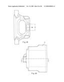
[0022]FIG. 9 is a perspective view of the kidney core of FIG. 6a.
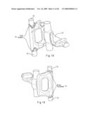
[0023]FIG. 10 is a perspective view of the finger core of FIG. 6a.
[0024]FIG. 11 is a side view of the finger and kidney cores of FIG. 6a.
[0025]FIG. 12 is a perspective view of the finger and kidney cores of FIG. 6a.
[0026]FIG. 13 is a perspective view of the finger and kidney cores of FIG. 6a.
[0027]FIG. 14 is a perspective view of the finger and kidney cores of FIG. 6a.
[0028]FIG. 15 is a perspective view of the finger and kidney cores of FIG. 6a.
[0029]FIG. 16 is a perspective view of the finger and kidney cores of FIG. 6a.
[0030]FIG. 17 is a perspective view of the finger and kidney cores of FIG. 6a.
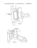
[0031]FIG. 18 is a perspective view of the finger and kidney cores of FIG. 6a.
[0032]FIG. 19 is a perspective view of the finger and kidney cores of FIG. 6a.
[0033]FIG. 20 is a perspective view of the finger and kidney cores of FIG. 6a.
[0034]FIG. 21 is a top view of the finger and kidney cores of FIG. 6a.
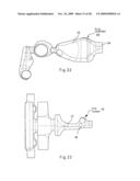
[0035]FIG. 22 is a top view of the finger and kidney cores of FIG. 6a.
[0036]FIG. 23 is a side view of the finger and kidney cores of FIG. 6a.
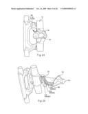
[0037]FIG. 24 is a side view of the finger and kidney cores of FIG. 6a.
[0038]FIG. 25 is a perspective view of the finger and kidney cores of FIG. 6a.
[0039]FIG. 26 is a side view of the finger and kidney cores of FIG. 6a.
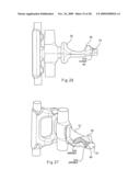
[0040]FIG. 27 is a perspective view of the finger and kidney cores of FIG. 6a.
[0041]FIG. 28 is a perspective view of the finger and kidney cores of FIG. 6a.
[0042]FIG. 29 is a side view of the finger and kidney cores of FIG. 6a.
[0043]FIG. 30 is a perspective view of the finger and kidney cores of FIG. 6a.
[0044]FIG. 31 is a perspective view of the finger and kidney cores of FIG. 6a.
[0045]FIG. 32 is a perspective view of the finger and kidney cores of FIG. 6a.
[0046]FIG. 33 is a perspective view of the finger and kidney cores of FIG. 6a.
[0047]FIG. 34 is a bottom view of the finger and kidney cores of FIG. 6a.
[0048]FIG. 35 is a perspective view of the finger and kidney cores of FIG. 6a.
[0049]FIG. 36 is a perspective view of the finger and kidney cores of FIG. 6a.
[0050]FIG. 37 is a perspective view of the finger and kidney cores of FIG. 6a.
[0051]FIG. 38 is a side view of the finger and kidney cores of FIG. 6a.
[0052]FIG. 39 is a side view of the finger and kidney cores of FIG. 6a.
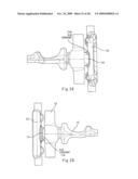
[0053]FIG. 40 is a side view of the finger and kidney cores of FIG. 6a.
[0054]FIG. 41 is a side view of the finger and kidney cores of FIG. 6a.
[0055]FIG. 42 is a perspective view of the finger and kidney cores of FIG. 6a.
[0056]FIG. 43 is a perspective view of the finger and kidney cores of FIG. 6a.
[0057]FIG. 44 is a top plan view of the finger and kidney cores of FIG. 6a.
[0058]FIG. 45 is a side plan view of the of the finger and kidney cores of FIG. 6a.
[0059]FIG. 46 is a side plan view of the finger and kidney cores of FIG. 6a.
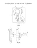
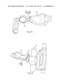
[0060]FIG. 47 is a side plan view of the kidney core and the C10 relief of FIG. 6a.
[0061]FIG. 48 is a side view of the finger core of FIG. 6a.
[0062]FIG. 49 is a side plan view of the knuckle of FIG. 1.
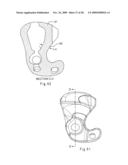
[0063]FIG. 50 is a cross sectional view along line C-C of FIG. 49.
[0064]FIG. 51 is a top plan view of the knuckle of FIG. 1.
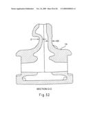
[0065]FIG. 52 is a cross sectional view of the interior of the knuckle of FIG. 1 along line D-D of FIG. 51.
DETAILED DESCRIPTION OF THE DRAWINGS AND THE PRESENTLY PREFERRED EMBODIMENTS
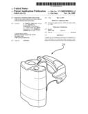
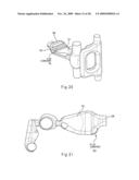
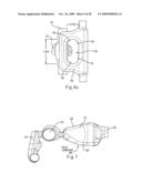
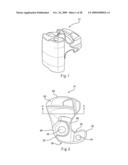
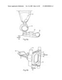
[0066]The goal of the present invention is to improve the strength and fatigue life of the knuckle by utilizing two unique cores. The completed knuckle 12 is shown in FIGS. 1-5 for reference. Referring to FIG. 6, the first specialized core is a finger core 10 and the second specialized core is a kidney core 12 that also includes a pivot pin core 13.
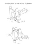
[0067]With respect to the front portion of the knuckle, the present invention utilizes a unique shape of the finger core 10, shown from different angles in FIGS. 6b, 6c, 10-20, 23-33 and 35-43. FIGS. 6-8 and 11-43 show the finger core 10 connected to the kidney core 12 to form the knuckle 21. FIG. 6 shows the finger core 10 about to be connected to the kidney core 12 through the interaction of an extension 14 on the finger core 10 and an opening 16 on the pivot pin core 13. FIGS. 9 and 10 show the finger core 10 alone.
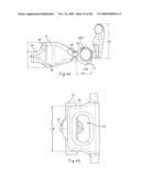
[0068]A completed knuckle 21 is shown in FIGS. 1-5. The finger core 10 forms the internal surfaces of the front face 26, nose 28, pulling face 30, heel 32 and flag hole 34 of the knuckle 21. The main section of the finger core 10 is preferably about 5.0'' wide by 7.9'' tall with a 2.1'' wide by 4.9'' tall rib 15 in the center. (FIGS. 6c and 45). The finger core 10 extends outward from the center to produce the 1.3'' flag hole 24 on both the top and bottom of the nose 28. The internal radii 36 of the finger core 10 are preferably smoothed to reduce stresses and increase fatigue life. The finger core 10 also includes a flag hole core 72.
[0069]The finger core 10 is designed such that an opening 18 forms a single thick rib 15 at the horizontal centerline of the resulting knuckle to more efficiently transfer the load to the pulling lugs of the knuckle and to reduce the stresses in the knuckle 21. As shown in the Figures, the number of corners 19 have been reduced down to four and larger radii than those present in the prior art are used in all four corners 19. Larger core fillets are also utilized. Exemplary dimensions of the opening 18 are shown in FIG. 6c as about 2.1'' wide and about 4.9'' high, but it is to be understood that other dimensions of this opening are also possible.
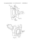
[0070]The interaction of these modifications results in lower stresses on the resulting rib 15, which can be seen in the finished knuckle 21 shown in FIGS. 1-5, especially in FIG. 5, which is a cross sectional view along line B-B of FIG. 4. Furthermore, FIG. 5 also offers the best view of the internal structure 23 created by the kidney 12 and pivot pin cores 13 along with the finger core 10.
[0071]With respect to the rear portion of the core, the present invention utilizes a unique kidney core 12 shape. Interior fillets 20 of the core 12 and the resultant wall thickness and profile have been maximized. Additionally, the buffing shoulder portions 22 of the core have been reduced in size to maximize wall thickness. Furthermore, the core support 24 at the tail of the knuckle 21 has been optimized in shape. The location of the tail support hole 25, the size, the shape of the hole, and then the wall thickness and the resulting interior fillets of these features have all been optimized to reduce stress concentrations while maintaining an acceptable weight of the knuckle 21.
[0072]For simplification, the measurements in this application have been rounded to the nearest tenth, although they are often shown in the Figures down to the hundredths or thousandths.
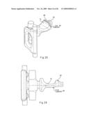
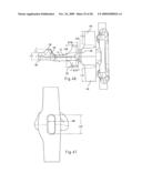
[0073]As shown in FIG. 44, a pivot pin core 13 includes about 1.7'' in diameter sections 42 that form pivot pin holes 38 on each end of the hub 40. The holes 38 travel toward a larger center C-10 relief that is formed by section 44 which is drafted outward at about 2 degrees on the pivot pin core 13 as shown in FIGS. 8 and 9. A cross-section of the C-10 relief at the knuckle center plane consists of a series of arcs and parabolic sections. This irregular center cross section 17 is roughly 2.5''×2.6''. As shown in FIG. 46, the C-10 relief 44 tapers back to the diameter of the pivot pin holes 38 at a distance of about 1.8'' away from each side of the knuckle center. As shown in FIG. 9, the C-10 relief 44 includes an about 2.5'' tall and about 1.0'' wide oblong slot 16 to receive the finger core lug 14. As shown in FIGS. 6 and 47, the finger core lug 14 is an about 2.5'' tall and about 1.0'' wide oblong post 14 and serves as the method for attaching the separate finger core 10 to the pivot pin section 13 before casting. The internal radiuses of the center C-10 section are preferably smoothed to reduce stresses and increase fatigue life.
[0074]The Figures also illustrate other areas where the kidney core 12, pivot pin 13 core, and the finger core 10 have been modified to further reduce stresses in the resulting knuckle. Unless otherwise specified, the measurements given for the adjusted radii in the present invention are given in inches (for example R.1'' or R1.2'')
[0075]The kidney core 12 creates the internal surfaces of the rear of the knuckle 21 from behind the pivot pin hole 38 to the tail 46. This areas is best illustrated in FIGS. 2 and 3. The kidney core 12 is part of the pivot pin core 13 and attached by an about 2.1'' tall by 0.7'' wide section 48. (FIGS. 44 and 46). The buffing shoulder cores 22 extend from this attachment point and measure approximately 0.78'' in diameter and have an overall height of about 4.0''. (FIG. 46). The buffing shoulder cores 22 each taper outward on into the main body of the kidney core 12. The main section of the kidney core 12 measures about 3.6'' across and about 1.0'' thick. (FIGS. 44 and 46). The modified dimensions of the kidney core 12 result in thicker wall sections in the rear section of the knuckle 21 and improves stresses and fatigue life.
[0076]The resulting wall thickness on the lock face 50 and just before the lock face 50 is about 1.4''. (FIG. 50). The resulting wall thickness on the tail stop side 52 of the kidney core 12 is about 1.2''. (FIG. 46). The resulting wall thickness below the kidney core 12 is about 0.67''. (FIG. 52). The resulting wall thickness above the kidney core 12 is about 0.5''. (FIG. 52).
[0077]Behind the main section of the kidney core 12 is the top pulling lug core 56 which extends about 1.2'' above the top of the main section 54. (FIG. 46). Just behind the main section 54 and before the top pulling lug core 56 the width of the kidney core 12 begins to taper down. The taper narrows down to a final width of about 1.6'' and 1.3'' tall before extending out of the tail 46. (FIGS. 44 and 46). The internal radii of the kidney core 12 section are preferably smoothed to reduce stresses and increase fatigue life.
[0078]Many changes have been made to specific radii of the finger and kidney cores as described in the following paragraphs. The sections that are references are shaded in each figure for clarity. As previously stated, the radius measurements below are in inches.
[0079]The radius 58 where the section 42 forming the pivot pin hole 38 meets the section 44 forming the C-10 relief is a constant R1.0'' for both the top and bottom radii (FIG. 8). The radii 60 on the outer top and bottom portions of the finger core 10 opposite of the flag hole core 72 are a constant R1.0'' (FIG. 11). The radius 62 on the outer portion of the finger core 10 opposite of the flag hole core 72 is a constant R.47'' (FIG. 6a). The radii 64 on the outer top and bottom of the finger core 10 are a constant R.47'' (FIG. 6 and FIG. 12).
[0080]The radii 66 on the front and back of the portion of the finger core 15 that forms the single thick rib are a constant R.55'' (FIG. 13 and FIG. 14). The top and bottom radii 68 on the portions of the finger core 10 that are near the pivot pin core 13 are a constant R.31'' (FIG. 15 and FIG. 16). The radii 70 the top and bottom flag hole core 72 are a constant R.75'' (FIG. 17). The radii 75 that fall between the top and bottom flag hole cores 72 and the main cylinder 77 that connects them have a constant R.50'' radii. The radii 74 that join the top and bottom flag hole cores 72 to the finger core 10 are a constant R.50'' (FIG. 19).
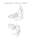
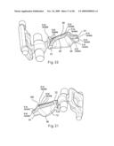
[0081]The radius 76 that forms the base 78 of the pulling lug core 36 in the kidney core 12 is a constant R.90'' (FIG. 20). The radii 80 on the each side of the kidney core 12 near the section 24 forming the rear core support hole are a constant R1.00'' (FIGS. 21 and 22). The radius 82 on the back of the top of the pulling lug core 36 on the kidney core 12 is a constant R.76'' (FIG. 26) The radius 84 on the kidney core 12 near the throat 85 is a constant R4.00'' (FIG. 7). The radius 86 on the throat side of the top of the top pulling lug core 36 of the kidney core 12 is a constant R1.00'' (FIG. 24). The radius 88 on the throat side of the top buffing shoulder core 22 of the kidney core 12 is a continuous variable radius fillet that starts at R.50'' and tapers to R.37 as it travels up the buffing shoulder core 22 (FIG. 25). The radius 90 that joins the back of the pulling lug core 56 to the section forming the rear support hole 24 is a constant R.50'' (FIG. 26). The radius 90 on the throat side behind the pulling lug core 36 of the kidney core 12 is a continuous variable radius fillet that starts at R.60'' and expands to R.64'' as it travels out to the section 24 that forms the core support hole (FIG. 27). The radius 94 on the top of the front of the pulling lug core 36 is a constant R.25'' (FIG. 28).
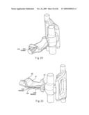
[0082]The radius 96 on the bottom of the kidney core 12 just before the pulling lug core 36 is a constant R1.00''(Figure 29). The radius 98 on the throat side of the bottom buffing shoulder core 22 of the kidney core 12 is a variable radius fillet that starts at R.45'' near the rear core support hole formed by the lug 24 and tapers to R.32'' near the pulling lug core 36 and then widens to R.50'' in the portion near the throat 85 and then tapers to R.38'' as it travels down the buffing shoulder core 22 (FIG. 30). The bottom radius 100 on the tail stop side of the kidney core 12 is a continuous variable radius fillet that starts at R.45'' near section 24 that forms the rear core support hole and widens to R.60'' as it travels toward the buffing shoulder core 22 (FIG. 31). The top radius 102 on the C-10 side of the kidney core 12 near the section 24 forming the rear core support hole is a constant R.64'' (FIG. 32). The top radius 104 on the C-10 side of the kidney core 12 is a variable radius fillet that starts at R.25'' at the pulling lug core 36 and widens to R.80'' as it travels toward the buffing shoulder core 22 (FIG. 33). The radius 106 on the front on the C-10 side of the kidney core 12 near the pivot pin core 13 is a constant R.75'' (FIG. 34). The radius 108 on the front of the top buffing shoulder core 22 on the C-10 side of the kidney core 12 near the pivot pin core 13 is a constant R.32'' (FIG. 35). The radius 110 on the front of the bottom buffing shoulder core 36 on the C-10 side of the kidney core 12 near the pivot pin core 13 is a constant R.35'' (FIG. 36). The radius 112 on the front of the top and bottom buffing shoulder core 36 on the throat side of the kidney core 12 near the pivot pin core 13 is a constant R.75'' (FIG. 37).
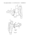
[0083]The fillet 114 where the post 14, used to attach the finger core 10 to the pivot pin core 13, where it joins with the finger core 10 is a constant R.50'' (FIG. 38 and 39). The fillets 116 that join the pivot pin core 13 to the kidney core 12 are a constant R.25'' (FIG. 40 and FIG. 41).
[0084]The top buffing shoulder core 36 consists of a single lofted surface 118 that starts on the flat surface of the kidney core 12 and travels up through the buffing shoulder core 36 (FIG. 42). The bottom buffing shoulder core 36 consists of a single lofted surface 120 that starts on the flat surface of the kidney core 12 and travels down through the buffing shoulder core 36 (FIG. 43).
[0085]It is intended that the foregoing detailed description be regarded as illustrative rather than limiting, and that it be understood that it is the following claims, including all equivalents, that are intended to define the spirit and scope of this invention.
User Contributions:
comments("1"); ?> comment_form("1"); ?>Inventors list |
Agents list |
Assignees list |
List by place |
Classification tree browser |
Top 100 Inventors |
Top 100 Agents |
Top 100 Assignees |
Usenet FAQ Index |
Documents |
Other FAQs |
User Contributions:
Comment about this patent or add new information about this topic:
Images included with this patent application:
 |  |
 |  |
 |  |
 |  |
 |  |
 |  |
 |  |
 |  |
 |  |
 |  |
 |  |
 |  |
 |  |
 |  |
 |
| Similar patent applications: | |
| Date | Title |
|---|---|
| 2013-08-22 | Central datum feature on railroad coupler body and corresponding gauges |
| 2012-02-16 | Railway coupler knuckle |
| 2010-12-23 | Rail road car draft fittings |
| 2013-10-31 | Toy car connection apparatus and method |
| 2012-10-11 | Coupler support mechanism |
| New patent applications in this class: | |
| Date | Title |
|---|---|
| 2016-05-19 | Railcar energy absorption/coupling system |
| 2015-11-12 | Coupler and method for production of a coupler with selectable configuration options |
| 2014-09-25 | Automated coupler positioning device |
| 2013-11-28 | Application of wear plate to articulated connector load bearing bottom surface |
| New patent applications from these inventors: | |
| Date | Title |
|---|---|
| 2018-04-19 | Railcar truck roller bearing adapter pad systems |
| 2016-04-21 | Railcar coupler core with vertical parting line and method of manufacture |
| 2016-02-04 | Railcar coupler knuckle cores and knuckles produced by said cores |
| 2015-07-02 | Railcar truck roller bearing adapter pad systems |
| 2015-07-02 | Railcar truck roller bearing adapter pad systems |
| Top Inventors for class "Railway draft appliances" | |
| Rank | Inventor's name |
|---|---|
| 1 | Jerry R. Smerecky |
| 2 | F. Andrew Nibouar |
| 3 | Thomas A. Marchese |
| 4 | Manuel Tavares |
| 5 | Zachary Ryan Brook |