Patent application title: WALKING ASSIST DEVICE
Inventors:
Hiroshi Kudoh (Wako-Shi, JP)
Assignees:
HONDA MOTOR CO., LTD.
IPC8 Class: AA61F278FI
USPC Class:
623 32
Class name: Prosthesis (i.e., artificial body members), parts thereof, or aids and accessories therefor leg suspender or attachment from natural leg
Publication date: 2009-11-12
Patent application number: 20090281636
Inventors list |
Agents list |
Assignees list |
List by place |
Classification tree browser |
Top 100 Inventors |
Top 100 Agents |
Top 100 Assignees |
Usenet FAQ Index |
Documents |
Other FAQs |
Patent application title: WALKING ASSIST DEVICE
Inventors:
Hiroshi Kudoh
Agents:
RANKIN, HILL & CLARK LLP
Assignees:
HONDA MOTOR CO., LTD.
Origin: WILLOUGHBY, OH US
IPC8 Class: AA61F278FI
USPC Class:
623 32
Patent application number: 20090281636
Abstract:
Provided is a walking assist device including a load transmit portion, a
ground contacting portion capable of using a commercially available shoe,
and a leg link disposed therebetween. The ground contacting portion is
composed of a footboard for supporting the shoe thereon. The footboard is
provided with a connection member connected to the leg link and a front
holding member and a rear holding member for stably holding a front vamp
portion and a rear vamp portion, respectively, of the shoe in an
anteroposterior direction. When a pressure sensor for detecting a
stepping force from a user is provided in the footboard, the front
holding member is located ahead of the pressure sensor.Claims:
1. A walking assist device having a load transmit portion, a ground
contacting portion and a leg link disposed between the load transmit
portion and the ground contacting portion, in which at least a part of a
user's body weight is supported by the leg link through the load transmit
portion, whereinthe ground contacting portion is composed of a footboard
for supporting thereon a shoe; andthe footboard is provided with a
connection member for connecting with the leg link, a front holding
member and a rear holding member for stably holding the shoe in a
anteroposterior direction.
2. The walking assist device according to claim 1, wherein the front holding member is configured to hold a front vamp portion of the shoe; and the rear holding member is configured to hold a rear vamp portion of the shoe.
3. The walking assist device according to claim 1, wherein the footboard is provided with a pressure sensor for detecting a stepping force by the user; and at least a part of the front holding member which presses the shoe from the upper is located ahead of the pressure sensor.
4. A ground contacting member of a walking assist device, wherein the ground contacting member comprises:a footboard for supporting a shoe;a connection member adapted to connect the footboard to the walking assist device; anda holding member adapted to secure the footboard to a shoe of a user.
5. The ground contacting member according to claim 4, wherein the holding member further comprises:a front holding member for holding a front vamp portion of the shoe; anda rear holding member for holding a rear vamp portion of the shoe.
6. The ground contacting member according to claim 5, wherein the front holding member further comprises:a first band;a second band; anda fastener provided on at least one of the first band and the second band,wherein the fastener is adapted to fasten the first band to the second band so as to allow the front holding member to vary in length.
7. The ground contacting member according to claim 5, wherein the footboard is provided with a pressure sensor for detecting a stepping force by the user; andat least a part of the front holding member which presses the shoe from the upper is located ahead of the pressure sensor.
8. The ground contacting member according to claim 5, wherein the rear holding member is adapted to wrap around the rear vamp portion of the shoe and is inclined toward a front vamp portion of the shoe.
9. The ground contacting member according to claim 6, wherein the rear holding member is adapted to wrap around the rear vamp portion of the shoe and is inclined toward a front vamp portion of the shoe.
Description:
PRIORITY CLAIM
[0001]The present application is based on and claims the priority benefit of Japanese Patent Application 2008-122164 filed on May 8, 2008, the contents of which are incorporated herein by reference in its entirety.
BACKGROUND OF THE INVENTION
[0002]1. Field of the Invention
[0003]The present invention relates to a walking assist device which assists a user in walking by alleviating a load acted on a leg thereof.
[0004]2. Description of the Related Art
[0005]Conventionally, there has been known a walking assist device having a load transmit portion, a ground contacting portion and a leg link disposed between the load transmit portion and the ground contacting portion, which assists a user in walking by alleviating a load acted on a leg thereof by means of supporting at least a part of the user's body weight by the leg link through the load transmit portion (for example, refer to Japanese Patent Laid-open No. 2007-20909).
[0006]In the conventional walking assist device, the ground contacting portion is composed of a special shoe provided with a connection member configured to connect with the leg link. Therefore, it is impossible to use a commercially available shoe in the conventional walking assist device, which makes it inconvenient in use since it is necessary to change to wear the special shoe every time when using the conventional walking assist device.
SUMMARY OF THE INVENTION
[0007]The present invention has been accomplished in view of the aforementioned problems, and it is therefore an object of the present invention to provide a walking assist device in which a commercially available shoe can be used.
[0008]To attain an object described above, the present invention provides a walking assist device having a load transmit portion, a ground contacting portion and a leg link disposed between the load transmit portion and the ground contacting portion, which at least a part of a user's body weight is supported by the leg link through the Load transmit portion, wherein the ground contacting portion is composed of a footboard for supporting thereon a shoe; and the footboard is provided with a connection member for connecting with the leg link, a front holding member and a rear holding member for holding the shoe stable in an anteroposterior direction.
[0009]According to the present invention, the shoe is laid on the footboard and is held by the front holding member and the rear holding member in the anteroposterior direction to become integrated with the footboard. The shoe is subsequently connected with the leg link through the footboard and the connection member connected to the footboard. Therefore, the walking assist device can be used to assist walking by using a commercially available shoe without using a special shoe connected to the connection member, which makes it convenient in use.
[0010]The front holding member and the rear holding member may be designed to hold a protruded portion of a sole of the shoe in the anteroposterior direction, respectively. However, it is possible that a shoe may not have the protruded portions in the anteroposterior direction. Therefore, by configuring the front holding member to hold a front vamp portion of the shoe and the rear holding member to hold a rear vamp portion thereof, it is advantageous to use various kinds of shoes in the walking assist device.
[0011]Further, when a pressure sensor is disposed in the footboard to detect a stepping force by the user, it is desirable to locate at least a part of the front holding member which presses the shoe from the upper ahead of the pressure sensor. Thereby, a pressing force by the front holding member will not act on the pressure sensor, and consequently, the detection error on the stepping force by the pressure sensor becomes small, improving the detection accuracy of the stepping force.
BRIEF DESCRIPTION OF THE DRAWINGS
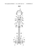
[0012]FIG. 1 is a side view of a walking assist device according to an embodiment of the present invention.
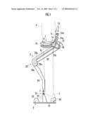
[0013]FIG. 2 is a front view of the walking assist device according to an embodiment of the present invention.
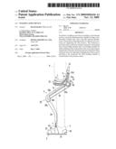
[0014]FIG. 3 is a perspective view of a ground contacting portion provided in the walking assist device according to an embodiment of the present invention.
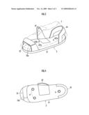
[0015]FIG. 4 is plan view of the ground contacting portion provided in the walking assist device according to an embodiment of the present invention.
DETAILED DESCRIPTION OF THE PREFERRED EMBODIMENTS
[0016]Hereinafter, a walking assist device according to an embodiment of the present invention will be described. As illustrated in FIG. 1 and FIG. 2, the walking assist device includes a seat member 1 on which a user P sits astride as a load transmit portion, a pair of left and right ground contacting portions 2 and 2, and a pair of left and right leg links 3 and 3 which are disposed between the seat member 1 and the two ground contacting portions 2 and 2, respectively.
[0017]Each leg link 3 can bend and stretch freely, composed of a first link member 32, and a second link member 34. The first link member 32 is connected to the seat member 1 through a first joint portion 31 at an upper end thereof, capable of swinging freely in the anteroposterior direction around the seat member 1. The second link member 34 is connected to a lower end of the first link member 32 through a rotary-typed second joint portion 33. A lower end of the second link member 34 is connected with a ground contacting portion 2 through a third joint portion 35 of a 3-axis structure.
[0018]The first link member 32 is provided with a driving source 4 for driving the second joint portion 33. Thereby, according to the rotation of the second joint portion 33 driven by the driving source 4, each leg link 3 is stretched to push the seat member 1 along a stretching direction upward so as to generate an assist force to support at least a part of a body weight of a user P (hereinafter, referred to as a body weight relieving assist force). The body weight relieving assist force generated in each leg link 3 is transmitted to the body trunk of the user P through the seat member 1 to relieve the load acted on a leg of the user P.
[0019]The driving source 4 is an electric motor provided with a reduction gear 4a, attached to a side surface of an upper end portion of the first link member 32. An output member of the reduction gear 4a, that is, a driving pulley 4b and a driven pulley 34a which is fixed concentrically with a joint axis 33a of the second joint portion 33 at the second link member 34 are connected through a wrapping transmission member 4c, such as a wire, a chain, a belt or the like. Thereby, a driving force output from the driving source 4 is transmitted to the second link member 34 through the wrapping transmission member 4c so that the second link member 34 swings around the joint axis 33a with respect to the first link member 32 to bend or stretch the leg link 3. Additionally, the first link member 32 is provided with a cover 32a configured to cover the wrapping transmission member 4c.
[0020]The seat member 1 is composed of a seat portion 1a, a support frame 1b, and a waist supporter 1c. The seat portion 1a is of a saddle shape to be seated by the user P. The support frame 1b is disposed below the seat portion 1a to support the seat portion 1a. The support frame 1b is configured to extend upward behind the seat portion 1a to form an uprising portion at a rear end thereof. The waist supporter 1c is disposed at the uprising portion. The waist supporter 1c is provided with a holding portion 1d of an arch shape to be held by the user P if necessary.
[0021]The first joint portion 31 at the upper end of each leg link 3 has a guide rail 31a of an arc shape disposed below the seat member 1. Then, each leg link 3 is movably engaged with the guide rail 31a via a plurality of rollers 31c pivotally attached to a slider 31b which is fixed to the upper end of the first link portion 32. In this way, each leg link 3 swings in the anteroposterior direction around the center of curvature of the guide rail 31a and the anteroposterior swing fulcrum of each leg link 3 functions as the center of curvature of the guide rail 31a.
[0022]Furthermore, the guide rail 31a is pivotally supported at the uprising portion formed at the rear end of the support frame 1b of the seat member 1 via a spindle 32d which is longitudinal in the anteroposterior direction. Therefore, the guide rail 31a is connected to the seat member 1, capable of swinging freely in the lateral direction. Accordingly, each leg link 3 is allowed to swing in the lateral direction, which enables the user P to abduct his/her legs. In addition, the center of curvature of the guide rail 31a and the axis line of the spindle 31d are both located above the seat portion 1a. Thereby, the seat member 1 can be prevented from inclining greatly in the vertical direction and in the lateral direction when the user P shifts his/her body weight.
[0023]Each ground contacting portion 2 is composed of a footboard 21 for supporting thereon a shoe 5 to be worn by each foot of the user P. The footboard 21 is provided with a connection member 22 connected to the lower end of the leg link 3 through the third joint portion 35. The footboard 21 is also provided with a front holding member 23 and a rear holding member 24 for holding the shoe 5 stable in the anteroposterior direction, that is, to prevent the shoe 5 from deviating in the anteroposterior direction.
[0024]Since the shoe 5 supported on the footboard 21 is held by the front holding member 23 and the rear holding member 24 in the anteroposterior direction, the footboard 21 is integral with the shoe 5. Consequently, the shoe 5 is essentially connected with the leg link 3, through the footboard 21 and the connected member 22 disposed at the footboard 21. Therefore, a commercially available shoe 5 can be used instead of a special shoe connected to the connection member. As a result thereof, it is convenient to use the walking assist device since it is not necessary to change to wear the special shoe every time when using the walking assist device.
[0025]Herein, it is possible to configure the front holding member 23 and the rear holding member 24 to hold a protruded portion from a sole of the shoe 5 in the anteroposterior direction, respectively. However, it is unable to cope with a shoe without such protruded portions in the anteroposterior direction in this configuration. Therefore, as illustrated in FIG. 3 of the present embodiment, by configuring the front holding member 23 to hold a front vamp portion of the shoe 5 and the rear holding member 24 to hold a rear vamp portion thereof, it is advantageous to use various kinds of shoes in the walking assist device.
[0026]The front holding member 23 is composed of a pair of laterally disposed bands 23a and 23a. Each band 23a is provided with a fastener. When the rear vamp portion of the shoe 5 is pushed to contact with the rear holding member 24, the pair of bands 23a and 23a of the front holding member 23 are tied up on the front vamp portion of the shoe 5 so as to hold the front vamp portion.
[0027]The rear holding member 24 is configured to have an inward inclination in the upward direction to have a surface contact with the rear vamp portion of the shoe 5. According thereto, the rear vamp portion of the shoe 5 can be certainly prevented from slipping out. Moreover, in case the rear holding member 24 is formed from a hard material, by attaching a friction material such as rubber or the like on the rear holding member 24 to be contacted by the rear vamp portion, the rear vamp portion of the shoe 5 can be further prevented from slipping out. It is possible to form the rear holding member 24 from a soft material such as rubber or the like to have the same shape as described in the present embodiment. It is also acceptable that the rear holding member 24 is composed of a pair of laterally disposed bands and each band is provided with a fastener so that the rear vamp portion of the shoe 5 is held by fastening the pair of bands.
[0028]In order to detect the stepping force from the user P, the footboard 21 is provided with three pressure sensors 6, in detail, two of them are located underneath the MP joints of the user's foot in the front, respectively, and one of them is located underneath the heel of the foot in the back. Moreover, a 2-axis force sensor 7 is built into the third joint portion 35. Detection signals from the pressure sensors 6 and the force sensor 7 are input to a controller 8 housed in the support frame 1b of the seat member 1. On the basis of the detection signals from the pressure sensors 6 and the force sensor 7, the controller 8 performs a walking assist control by controlling the driving source 4 to drive the second joint portion 33 of the leg link 3 to generate the body weight relieving assist force.
[0029]The body weight relieving assist force is acted on a connection line (hereinafter, referred to as a reference line) joining a swing fulcrum of the leg link 3 with respect to the first joint portion 31 in the anteroposterior direction and a swing fulcrum of the leg link 3 with respect to the third joint portion 35 in the anteroposterior direction. In the walking assist control, the actual body weight assist force acted on the reference line (accurately, a resultant force between the body weight relieving assist force and a force generated by the weights of the seat member 1 and each leg link 3) is calculated based on detection values of forces in the two-axis direction detected by the force sensor 7. Thereafter, on the basis of the stepping force detected by the pressure sensors 6 in each ground contacting portion 2, a ratio of the stepping force of each leg with respect to the resultant force from both legs of the user P is calculated. Then, a desired control value of the body weight relieving assist force which should be generated for each leg link 3 is calculated by multiplying a predefined value of the body weight relieving assist force by the calculated ratio of the stepping force of each leg. Subsequently, the driving source 4 is controlled so as to make the actual body weight relieving assist force calculated on the basis of the detection values by the force sensor 7 approximate to the desired control value.
[0030]Herein, if a pressing force generated by the front holding member 23 is acted on the pressure sensors 6, the detection accuracy of the stepping force will be deteriorated. Therefore, as illustrated in FIG. 4, the front holding member 23 is located ahead of the pressure sensors 6 in the front in the present embodiment. According thereto, the pressing force by the front holding member 23 is not acted on the pressure sensors 6, the detection error becomes small, and consequently, the detection accuracy of the stepping force is improved. Note that as long as a part of the front holding member 23 which holds the shoe 5 from the upper is located ahead of the pressure sensors 6, it is acceptable that a basal connection portion of the front holding member 23, through which the front holding member 23 is jointed to the ground contacting portion 2, is located behind the pressure sensors 6. In other words, even though the basal connection portion of the front holding member 23 is located behind the pressure sensors 6, the pressing force will not be acted on the pressure sensors 6 from above, therefore, the detection accuracy of the stepping force will not be affected. Herein, the part of the front holding member 23 which holds the shoe 5 from the upper is referred to as the part which has contact to the shoe 5 and applies a downward force to the shoe 5.
[0031]Although the embodiment of the present invention has been described hereinabove with reference to the drawings, the present invention is not limited thereto. For example, in the above-mentioned embodiment, the leg link 3 is configured as a telescopic link with a rotary second joint portion 33 disposed therein; it is acceptable that the leg link is configured as a telescopic link having a linear second joint portion. In addition, it is possible to adopt a harness mounted around the waist of the user as the load transmit portion. Moreover, in order to assist the walking of a handicapped user whose one leg is crippled due to bone fracture or the like, it is possible to leave only one leg link of the left and right leg links 3 and 3 in the above-mentioned embodiment corresponding to the crippled leg of the user by removing the other.
User Contributions:
comments("1"); ?> comment_form("1"); ?>Inventors list |
Agents list |
Assignees list |
List by place |
Classification tree browser |
Top 100 Inventors |
Top 100 Agents |
Top 100 Assignees |
Usenet FAQ Index |
Documents |
Other FAQs |
User Contributions:
Comment about this patent or add new information about this topic:
Images included with this patent application:
 |  |
 |  |
| Similar patent applications: | |
| Date | Title |
|---|---|
| 2009-02-19 | Controller for walking assistance device |
| 2009-12-17 | Control device for walking assist device |
| 2010-01-14 | Control device for walking assistance device |
| 2010-01-14 | External walking assist device for those with lower leg injuries |
| 2010-05-06 | Guide mechanism and walking assist device |
| New patent applications in this class: | |
| Date | Title |
|---|---|
| 2016-07-14 | Microminiature chainmail interface between skin and a transcutaneous prosthetic device and a method of manufacture |
| 2016-06-30 | Assisting torque setting method and apparatus |
| 2016-05-26 | Assisting torque setting method and apparatus |
| 2016-04-14 | Transdermal intraosseous device |
| 2016-03-10 | Variable-mechanical-impedance artificial legs |
| New patent applications from these inventors: | |
| Date | Title |
|---|---|
| 2011-11-24 | Walking assistance device |
| 2010-05-13 | Walking assistance device |
| 2010-05-06 | Ankle joint structure of walking assistance device |
| 2009-11-26 | Walking assist device |
| Top Inventors for class "Prosthesis (i.e., artificial body members), parts thereof, or aids and accessories therefor" | |
| Rank | Inventor's name |
|---|---|
| 1 | Anton G. Clifford |
| 2 | Yunbing Wang |
| 3 | Jan Weber |
| 4 | Chad Glerum |
| 5 | Robert Metzger |