Patent application title: FORCE VENTILATED AND HEATED GARMENT
Inventors:
Lloyd Richardson (Wesley Chapel, FL, US)
IPC8 Class: AA41D13005FI
USPC Class:
2458
Class name: Guard or protector body cover thermal body cover
Publication date: 2009-11-05
Patent application number: 20090271917
Inventors list |
Agents list |
Assignees list |
List by place |
Classification tree browser |
Top 100 Inventors |
Top 100 Agents |
Top 100 Assignees |
Usenet FAQ Index |
Documents |
Other FAQs |
Patent application title: FORCE VENTILATED AND HEATED GARMENT
Inventors:
Lloyd Richardson
Agents:
Maxey Law Offices, PLLC
Assignees:
Origin: CLEARWATER, FL US
IPC8 Class: AA41D13005FI
USPC Class:
2458
Patent application number: 20090271917
Abstract:
A force ventilated and heated garment including a garment body and a
self-contained forced ventilator removably attachable to the garment
body. A plurality of air flow channels are arranged along the garment
body and are connected to an air inlet. The forced ventilator includes
one or more blowers that draw ambient air into the ventilator and
discharges into the air inlet connected to the air flow channels. A
heating element is positioned in the ventilator to heat air passing
through it before being discharged into the air inlet. A controller is
provided for allowing a user to control the amount of heat generated by
the heating element. A sealable vent extends through the garment for
venting the interior of the garment should it become to warm.Claims:
1. A force ventilated and heated garment to be worn by a user, comprising,
in combination:a garment body having an exterior and an interior;a
plurality of air flow channels arranged along said garment body adapted
to distribute air to said interior of said garment body;an air inlet
through said garment body, wherein said plurality of air flow channels
are in fluid communication with said air inlet;a forced ventilator
housing defining an air flow passage having an air flow passage inlet and
an air flow passage outlet;one or more blowers arranged in said air flow
passage and operable to cause air flow through said air flow passage
where air is drawn in from said air flow passage inlet and discharged
from said air flow passage outlet;one or more heating elements arranged
in said air flow passage and operable to heat said air flow;a power
source carried by said forced ventilator housing;a controller carried by
said forced ventilator housing and connecting said power source to said
one or more blowers and said heating element; anda coupling means for
detachably connecting said force ventilator housing to said garment body
with said air flow passage outlet in fluid communication with said air
inlet.
2. The garment of claim 1, wherein said garment body has a first inner layer of an air permeable material, a second inner layer of an insulating material, and an exterior layer; and wherein said plurality of flow channels are arranged between said first inner layer and said second inner layer.
3. The garment of claim 1, further comprising:one or more sealable vents extending through said garment body connecting said exterior to said interior for venting air from said interior to said exterior.
4. The garment of claim 1, wherein said garment body has a torso portion defining a waist opening and a head opening, and two arm portions having each having a wrist opening.
5. The garment of claim 4, further comprising a hood portion.
6. The garment of claim 4, wherein said garment body has a first inner layer of an air permeable material, a second inner layer of an insulating material, and an exterior layer; and wherein said plurality of flow channels are arranged between said first inner layer and said second inner layer; and wherein said waist opening and said wrist openings each comprises an elastic cuff.
7. The garment of claim 6, further comprising:one or more sealable vents on each of said two arm portions approximate said wrist opening that extend through said exterior layer and said second interior layer, thereby connecting said exterior to said interior for venting air from said interior to said exterior.
8. A force ventilated and heated garment to be worn by a user, comprising, in combination:a body garment having a torso portion defining a waist opening and a head opening, and two arm portions having each having a wrist opening, wherein said waist opening and said wrist openings each comprises an elastic cuff;said body garment further having a first inner layer of an air permeable material, a second inner layer of an insulating material, and an exterior layer;a plurality of air flow channels arranged along said garment body between said first inner layer and said second inner layer that are adapted to distribute air to said interior of said garment body;an air inlet through said exterior layer and said second inner layer, wherein said plurality of air flow channels are in fluid communication with said air inlet;one or more sealable vents on each of said two arm portions approximate said wrist opening that extend through said exterior layer and said second interior layer, thereby connecting said exterior to said interior for venting air from said interior to said exterior;a forced ventilator housing defining an air flow passage having an air flow passage inlet and an air flow passage outlet;one or more blowers arranged in said air flow passage and operable to cause air flow through said air flow passage where air is drawn in from said air flow passage inlet and discharged from said air flow passage outlet;one or more heating elements arranged in said air flow passage and operable to heat said air flow;a power source carried by said forced ventilator housing;a controller carried by said forced ventilator housing and connecting said power source to said one or more blowers and said heating element; anda coupling means for detachably connecting said force ventilator housing to said garment body with said air flow passage outlet in fluid communication with said air inlet.
Description:
FIELD OF THE INVENTION
[0001]The present invention relates generally ventilated garments, and more particularly, relating to a force ventilated and heated garment having a self-contained ventilator assembly that is removably attachable to a garment for distributing heated air through the garment.
BACKGROUND OF THE INVENTION
[0002]It is well known that subjecting a person to prolonged periods of cold conditions can lead to various levels of discomfort, injury or health effects, which are collectively known as cold stress. The hazardous effects of cold stress on the body may include minor to severe discomfort, numbness, frostbite, hypothermia and decreased physical and mental performance. When operating machinery or driving vehicles, such as snowmobiles or motorcycles where acute mental and physical performance is imperative to safety, there is a need to prevent cold stress to the operator when subjected to cold environments.
[0003]Forced ventilated cooling garments, forced ventilated heating garments, and electrically heated garments are known in the prior art. More specifically, these garments heretofore devised and utilized for the purpose of cooling or heating a user are known to consist of a myriad of designs encompassed by the crowded field which have been developed for the fulfillment of countless objectives and requirements.
[0004]However, there still exists a need for a forced heated garment of an improved construction for providing heat to a user during operation of a motor vehicle, such as a motorcycle or snowmobile in cold environments which does not impair the movement of the operator during use, which provides a detachable forced ventilation assembly permitting the garment to be worn during times of low likelihood of cold stress, and which provides the user the ability to vent the garment.
SUMMARY OF THE INVENTION
[0005]The preferred embodiments of the present invention addresses this need by providing a force ventilated and heated garment of an improved construction having a self-contained forced ventilator unit that is detachably mountable to the garment for providing heat to the user in cold climates and which can be removed from the garment in warm climates. The forced ventilator unit is attachable to the garment in a manner that does not interfere with the user in operating a motor vehicle or other machinery.
[0006]To achieve these and other advantages, in general, in one aspect, a force ventilated and heated garment is provided. The garment includes, in combination, a garment body having an exterior and an interior. A plurality of air flow channels are arranged along the garment body and are adapted to distribute air to the interior of the garment body. The plurality of air flow channels are in fluid communication with an air inlet. A forced ventilator housing has an air flow passage with an air flow passage inlet and an air flow passage outlet. One or more blowers are arranged in the air flow passage and are operable to cause an air flow through the air flow passage where air is drawn in from the air flow passage inlet and then discharged from the air flow passage outlet.
[0007]A heating element is arranged in the air flow passage and is operable to heat the air flow. A power source carried by the forced ventilator housing is connected to the one or more blowers and the heating element by a controller. A coupling means is provided for detachably connecting the force ventilator housing to the garment body with the air flow passage outlet in fluid communication with the air inlet.
[0008]In general, in another aspect, the garment body has a first inner layer of an air permeable material, a second inner layer of an insulating material, and an exterior third layer, and the plurality of flow channels are arranged between the first inner layer and the second inner layer.
[0009]In general, in another aspect, the force ventilated and heated garment includes one or more sealable vents extending through the garment body connecting the exterior to the interior for venting air from the interior to the exterior.
[0010]There has thus been outlined, rather broadly, the more important features of the invention in order that the detailed description thereof that follows may be better understood and in order that the present contribution to the art may be better appreciated.
[0011]Numerous objects, features and advantages of the present invention will be readily apparent to those of ordinary skill in the art upon a reading of the following detailed description of presently preferred, but nonetheless illustrative, embodiments of the present invention when taken in conjunction with the accompanying drawings. The invention is capable of other embodiments and of being practiced and carried out in various ways. Also, it is to be understood that the phraseology and terminology employed herein are for the purpose of descriptions and should not be regarded as limiting.
[0012]As such, those skilled in the art will appreciate that the conception, upon which this disclosure is based, may readily be utilized as a basis for the designing of other structures, methods and systems for carrying out the several purposes of the present invention. It is important, therefore, that the claims be regarded as including such equivalent constructions insofar as they do not depart from the spirit and scope of the present invention.
[0013]For a better understanding of the invention, its operating advantages and the specific objects attained by its uses, reference should be had to the accompanying drawings and descriptive matter in which there is illustrated preferred embodiments of the invention.
BRIEF DESCRIPTION OF THE DRAWINGS
[0014]The accompanying drawings, which are included to provide further understanding of the invention and are incorporated in and constitute a part of this specification, illustrate preferred embodiments of the invention and together with the description serve to explain the principles of the invention, in which:
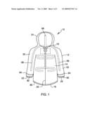
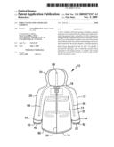
[0015]FIG. 1 is a front diagrammatic view of the force ventilated and heated garment constructed in accordance with the principles of the present invention;
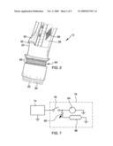
[0016]FIG. 2 is a partial perspective view of a sleeve portion of the garment illustrating the multi-layer construction of the garment, a vent system and details of the sleeve cuff;
[0017]FIG. 3 is a diagrammatic rear perspective view of the garment showing a self-contained forced ventilator assembly exploded from a receiving frame attached to the garment;
[0018]FIG. 4 is a partial diagrammatic rear elevation view of the forced ventilator attached to the garment;
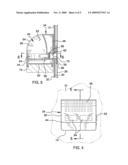
[0019]FIG. 5 is a cross-sectional view through the forced ventilator and the garment taken along line 5-5 in FIG. 4;
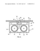
[0020]FIG. 6 is a cross-sectional view through the forced ventilator and the garment taken along line 6-6 in FIG. 5; and
[0021]FIG. 7 is a schematic view of the control system of the forced ventilator.
DETAILED DESCRIPTION OF THE INVENTION
[0022]Reference will now be made in detail to the preferred embodiments of the present invention, examples of which are illustrated in the accompanying drawings. Referring to FIG. 1, there is shown a forced ventilated and heated garment 10 constructed in accordance with the principals of the present invention. The garment 10 is depicted as a jacket having a body 12 with a torso portion 14 with a waist opening 16 and a neck opening 18, a pair of long sleeves 20 with wrist openings 22, and optionally a hood portion 24 and a front closeable opening 26. As shown in FIG. 2, the body 12 has an inner first layer 28 comprising an air permeable material, which may be an open mesh material. Adjacent the inner first layer 28 is an inner second layer 30 comprising a heat insulating material, which may be an open or closed cell foam material. The body 12 further has an outer third layer 32 adjacent in the inner second layer 30.
[0023]With reference to FIG. 3, a self-contained force ventilator unit 34 is removably attachable to the body 12 of the garment 10 by a coupling means 36. The coupling means 36 may comprise a frame 38 that is permanently secured to the body 12 to which the ventilator unit 34 is operably engagable. The frame 38 may comprise a semi-flexible material to conform to the contour of the body 12 and the user. In this particular example, the ventilator unit 34 is slidably received by the frame 38 through a tongue and groove arrangement, and is retained in the frame by a spring loaded tab 40 that is receivable by a slot 42. It is contemplated that the ventilator unit 38 may be operably engagable to the frame 38 by a numerous different methods and should not be limited solely to the tongue and groove arrangement that is depicted in the drawings.
[0024]With further reference to FIGS. 4, 5 and 6, the ventilator unit 34 includes a housing 44 having a top-front wall 46, a rear wall 48, a bottom wall 50 and a pair of side walls 52. The housing 44 defines an internal air flow passage 46 with an air passage inlet 54 through wall 46 and an air passage outlet 56 through wall 48. The air flow passage 46 is divided by an internal wall 58 into an low pressure portion 60 and high pressure portion 62. One or more blowers 64 are arranged in the air flow passage 46 in the low pressure portion 60. The blowers 64 operate to draw ambient air into the air flow passage 46 through the air inlet 54 and discharge air under pressure into the high pressure portion 62 and through the air passage outlet 56.
[0025]One or more heating elements 66 are located within the air flow passage 46 across the flow of air therethrough. Ideally, the heating elements 66 is located down stream of the blowers 64 and upstream of the air passage outlet 56. Air flowing through the air flow passage 46 is heated as it passes across the heating element 66. The heating element 64 may be an electrical resistance-type heating element.
[0026]With reference now to FIGS. 1, 2 and 3, a plurality of air flow channels 68 are arranged along the body 12 for distributing heated air through the garment 10 and into the interior thereof. The air flow channels 68 are positioned between the inner first layer 28 and the inner second layer 30. The air flow channels 68 may comprises plurality of perforated tubes or alternatively may be sewn into the body 12. The air flow channels 68 are in fluid communication with an air inlet 70 positioned through the body 12 and located within the perimeter of the frame 38. The air inlet 70 may extend only through the second and third layers 30 and 32 of the body 12.
[0027]With the ventilator unit 34 secured to the garment 10, the air passage outlet 56 is arrange in fluidic communication with the air inlet 70 that is connected to the plurality of air flow channels 68. Heated air that is discharged through the air passage outlet 56 is passes through the air inlet 70 and into the air flow channels 68 where it is then distributed through out the garment 10 and finally discharged into the interior of the garment. A sealing element 72 may be arrange around the air inlet 70 to form an air tight seal between the air passage outlet 56 and the air inlet 70.
[0028]A power source 74 is provided to power both the blowers 64 and the heating element 66. The power source 68 may be a rechargeable battery pack, and may also be detachably secured to the housing 44 of the ventilator unit 34. Optionally, the power source 74 may be received internally of the housing 44, such as in a battery compartment (not shown). In FIG. 7, the power source 74 is connected to the blowers 64 and the heating element 66 by a controller 76. The controller 76 may be an on/off switch 78 and a potentiometer 80 to control the amount of current flowing to the heating 66 element to adjust the level the air is heated. The on/off switch 78 and the potentiometer 80 are attached to the housing 44 in a location that is conveniently reached by the user. The on/off switch 78 and the potentiometer 80 may be provided as a single switch element.
[0029]With reference to FIGS. 1 and 2, each wrist opening 22 may be include an elastic cuff 82, and the waist opening 16 may include an elastic cuff 85 to seal the respective openings to the body of the user. The body 12 may further include one or more vent structures 84 to vent the interior of the garment to the exterior to reduce the heat within the interior. A vent 84 may be located on each arm portion 20, and may also be located approximate the wrist opening 22. The vent 84 may extend through the second and third layers 30 and 32 of the body 12. The vent 84 may be sealed by a fastener 86 arranged about the upper and lower peripheries of the vent. The fastener 86 may be a slide-type fastener as shown, or alternatively could be a hook-and-loop type fastener.
[0030]With reference to FIG. 3, a flap 88 may be provided to cover the frame 38 when the ventilator unit 34 is removed from the garment 10. The flap 88 is shown rolled-up below the frame 38 and secured with a pair of straps 90. The flap 88 may be secured to the garment by a first hook-and-loop fastener 92 arranged around the outer perimeter of the frame 38 and a second hook-and-loop fastener 94 arranged around the periphery of the flap. When the ventilator unit 34 is not being used, the flap 88 provides a decorative and protective covering for the frame 38.
[0031]A number of embodiments of the present invention have been described. Nevertheless, it will be understood that various modifications may be made without departing from the spirit and scope of the invention. Accordingly, other embodiments are within the scope of the following claims.
User Contributions:
comments("1"); ?> comment_form("1"); ?>Inventors list |
Agents list |
Assignees list |
List by place |
Classification tree browser |
Top 100 Inventors |
Top 100 Agents |
Top 100 Assignees |
Usenet FAQ Index |
Documents |
Other FAQs |
User Contributions:
Comment about this patent or add new information about this topic:
Images included with this patent application:
 |  |
 |  |
 |  |
| Similar patent applications: | |
| Date | Title |
|---|---|
| 2009-03-26 | Ventilated double-closure garment |
| 2011-07-28 | Tailored and vented facial garment |
| 2011-07-14 | Visor adapted for helmet or head engagement |
| 2010-03-18 | Glove that can be heated by the user's breath |
| New patent applications in this class: | |
| Date | Title |
|---|---|
| 2016-12-29 | Flame resistant fabric and garments made therefrom |
| 2016-03-03 | Light-weight, flame-resistant coveralls with knitted, stretchable portion for upper torso |
| 2015-12-31 | Full body coat |
| 2015-10-22 | Flame resistant fabric with anisotropic properties |
| 2014-09-25 | Flameproof spun yarn, fabric, clothes and flameproof work clothes |
| Top Inventors for class "Apparel" | |
| Rank | Inventor's name |
|---|---|
| 1 | William L. Grilliot |
| 2 | Mary I. Grilliot |
| 3 | David Turner |
| 4 | Patricia K. Waters |
| 5 | Caleb Clark Crye |