Patent application title: FIBERGLASS LAWN EDGING
Inventors:
Peter Caceres (Keller, TX, US)
John Fakhari (Keller, TX, US)
IPC8 Class: AB29C4706FI
USPC Class:
264148
Class name: With severing, removing material from preform mechanically, or mechanically subdividing workpiece forming continuous work followed by cutting extruding followed by cutting to length
Publication date: 2009-09-24
Patent application number: 20090236768
Inventors list |
Agents list |
Assignees list |
List by place |
Classification tree browser |
Top 100 Inventors |
Top 100 Agents |
Top 100 Assignees |
Usenet FAQ Index |
Documents |
Other FAQs |
Patent application title: FIBERGLASS LAWN EDGING
Inventors:
Peter Caceres
John Fakhari
Agents:
ERICKSON, KERNELL, DERUSSEAU & KLEYPAS, LLC
Assignees:
Origin: KANSAS CITY, MO US
IPC8 Class: AB29C4706FI
USPC Class:
264148
Abstract:
A system of fiberglass lawn edging materials. The pultruded fiberglass
system provides a lawn edging that is durable and easy to install. The
fiberglass edging material comes in a long, flat shape that can be rolled
up for ease of display and transport. The system includes metal or
pultruded fiberglass stakes. The system includes a integral veil that
allows for a variety of surface treatments.Claims:
1. A process for manufacturing a fiberglass product comprising the steps
of:sandwiching a layer of unidirectionally oriented fiberglass strands
between two continuous mats of randomly oriented fiberglass strands to
form a fiber assembly;pulling the fiber assembly through a vat of
thermoset resin to form a wet core;applying a veil layer on both sides of
the wet core to form a raw assembly;pulling the raw assembly through a
heated die to form a pultruded strip;cutting the pultruded strip exiting
the dye to a selected length and rolling the pultruded strip cut to a
selected length into a roll.
2. The process as in claim 1 further comprising the step of binding said roll for shipment.
3. A process of manufacturing a fiberglass lawn edging system including the steps of pultruding a first section of fiberglass lawn edging by pulling an inner layer of fiberglass strands and two mats of randomly oriented glass fibers through liquid thermoset resin to form a wet core, covering said wet core with a decorative covering layer to form a raw section of edging and then heating said raw section of edging in a continuous process to harden said wet core, cutting said first section to length and then forming a roll from said first section and binding said roll for shipment.
Description:
CROSS REFERENCE TO PRIOR APPLICATION
[0001]The present application is a continuation application of U.S. patent application Ser. No. 10/234,991 filed Sep. 4, 2002, which claims priority from provisional application No. 60/329,793 filed Oct. 16, 2001, which is hereby incorporated into the present application by reference.
BACKGROUND OF THE INVENTION
[0002]The present invention relates to material provided for lawn and garden edging. Lawn edging is typically used to provide a sharp line between two areas of diverse plant growth in a lawn. In the past a variety of edging systems have been developed.
[0003]U.S. Pat. No. 1,977,021 discloses a sheet metal edging. While sheet metal is flexible and inexpensive it tends to corrode quickly, particularly in this application where lawn and garden fertilizers are often being used.
[0004]U.S. Pat. No. 5,941,018 discloses a lawn edging system including stakes used to hold the edging in place. This patent discloses many of the common materials used for edging including molded or extruded plastic and aluminum extrudate. Each of these materials has problems. Most plastics hold up well in ground contact, but do not hold up well when exposed to UV light from the sun and to freezing conditions. Lawn edging must also be tough because lawn and garden equipment such as lawn mowers and bladed lawn edgers are often used right up next to the edging material. Most plastics are not tough enough to last more than a few seasons in this kind of abusive environment. While aluminum is tougher then plastic, it must be coated to look good and resist the corrosion of fertilizers. The coating system usually fails after just a few seasons.
[0005]It is therefore desirable to have a lawn edging system that is attractive, tough, corrosion and UV resistant, inexpensive to manufacture, and easy to install.
SUMMARY OF THE INVENTION
[0006]The invention consists of pultruded fiberglass edging. The resulting edging material is flexible yet tough and resistant to a variety of environmental factors.
[0007]Unlike steel and even aluminum, pultruded fiberglass is lightweight and easy to machine using just hand tools. Fiberglass also resists corrosion even in soil with fertilizer. Fiberglass is tougher then plastic and is also resistant to UV degradation. The present invention envisions a boarder installation method where the edging material and stakes are bundled together. These bundles would be the most efficient way to ship the raw materials to build the system. Once on the job site the bundles would be opened up and the system could be installed.
[0008]Once a length of edging has been pultruded it can be rolled up and packaged as a roll. During installation the material is flexible enough to be bent around obstacles. Connectors are available to join lengths of material and to make corners. Stakes can be of metal, plastic or of pultruded fiberglass material.
BRIEF DESCRIPTION OF THE DRAWINGS
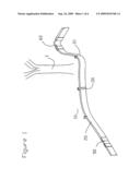
[0009]FIG. 1 is a view of the edging system installed
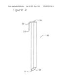
[0010]FIG. 2 is a view of a stake
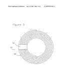
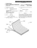
[0011]FIG. 3 is a view of a coil of edging material
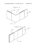
[0012]FIG. 4 shows a corner connector
[0013]FIG. 5 shows a straight connector
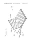
[0014]FIG. 6 shows the layers of the edging
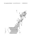
[0015]FIG. 7 shows the manufacturing process
DESCRIPTION OF A PREFERRED EMBODIMENT OF THE INVENTION
[0016]FIG. 1 shows the edging system installed in a typical application. The edging system (10) includes a length of flexible fiberglass edging (20). The lower portion of the edging (20) is not shown in this view as it is underground in the typical application. The edging (20) is flexible and is shown bending at (21) to go around an obstacle such as a tree (T). The system includes stakes (30), straight connectors (50), and corner connectors (60). The stakes (30) can be of any conventional type, a special matching fiberglass stake is shown. The system can be made in a variety of different colors and decorative patterns.
[0017]FIG. 2 shows a matching pultruded fiberglass stake (30). The stake (30) has a sharpened end (31) and a hole (34) that passes through the length. A clip (32) with an extended arm (33) is held to the stake (30) by a screw or rivet (36) which uses the hole (34) as a pilot hole. For example, the stake (30) can be driven into position next to the edging (20) and then the clip (32) positioned over the edging (as shown in FIG. 1) and a screw (36) can be driven into the stake (30) to hold the clip in place. This fiberglass stake would have many of the same advantages stated above for fiberglass and would match the edging material (20) however any conventional stake material would also work.
[0018]FIG. 3 shows the edging (20) rolled up ready for shipping to the installation location. Rolling the long pultrusions make them easy to handle and ship. The roll (40) is held together with a piece of strapping tape (42). This roll (40) can be boxed or displayed in a store without a box. Typically the rolls might come in lengths of 25 feet to 100 feet.
[0019]FIG. 4 shows how a corner connector (60) works. The connector (60) includes two slots (62) for accepting an end of the edging (20). The connector (60) includes a bend (64) that is shown as 90 degrees. By placing two edging strips in each slot (62) a sharp 90 degree bend can be created. Other angles such as 45 degree would also be possible. This connector allows the system to create a sharp corner, where the pultruded fiberglass edging (20) typically cannot bend at a sharp angle. This corner connector (60) can be made of matching pultruded fiberglass or from an accent material.
[0020]FIG. 5 shows a straight connector (50). The connector (50) includes two slots (52) for accepting an end of the edging (20). This connector allows for splicing two pieces of edging (20) together to make a long run of edging.
[0021]FIG. 6 shows an exploded view of the layers of the edging (20). The exterior veil layer (202) on both sides is a polyester material that can be printed with patterns to give it the appearance of any desirable material such as brick (as shown), stone or wood. Layer (204) is the continuous strand mat. This layer consists of a thin mat of randomly oriented fiberglass strands. There are two layers (204) which sandwich the center (rovings) layer (206) which consists of a mat of long fibers oriented lengthwise with the length of the edging material (20).
[0022]Referring to FIG. 7, in the manufacturing process (300), the unidirectional rovings layer (206) is sandwiched between the two continuous strand mats (204) and this assembly is pulled through a vat of thermoset resin (302). The veil (202) is then applied to both sides and the assembly is pulled through a heated die (304). The lengths of edging (20) are cut by cut off saw (306) as the material comes out of the puller (308).
[0023]In use, a trench one to two inches deep is dug where the system is to be installed. Place one end of the edging roll (40) at the desired beginning of the edging trench (not shown) and secure by driving a stake (30) down beside the edging as shown in FIG. 1. The edging is then unrolled and staked at intervals of a few feet. For long runs involving multiple rolls (40) the straight connection section (50) can be used to provide an attractive splice or if desired the ends of two rolls can simply overlap to create an attractive, continuous boarder. At locations where a tight 90 degree bend is required, such as where two sidewalks come together, a corner connector (60) can be used. The edging (20) can be cut to length using tools used to cut conventional metal edging such as tin snips or a hack saw.
User Contributions:
comments("1"); ?> comment_form("1"); ?>Inventors list |
Agents list |
Assignees list |
List by place |
Classification tree browser |
Top 100 Inventors |
Top 100 Agents |
Top 100 Assignees |
Usenet FAQ Index |
Documents |
Other FAQs |
User Contributions:
Comment about this patent or add new information about this topic:
| People who visited this patent also read: | |
| Patent application number | Title |
|---|---|
| 20130216493 | PEG OR PEG BLOCK COPOLYMERS FOR TREATING COLORECTAL CANCER |
| 20130216492 | Method for Searching for Malodor Control Agent, Malodor Control Agent, and Malodor Control Method |
| 20130216491 | COMPOSITION FOR CLEANING SCALP AND HEAD HAIR |
| 20130216490 | HAIR TREATMENT AGENTS HAVING LOW-DOSE OLIGOPEPTIDES |
| 20130216489 | Polysaccharide Products With Improved Performance And Clarity In Phosphate Ester Surfactant-Based Aqueous Formulations And Process For Preparation |
Images included with this patent application:
 |  |
 |  |
 |  |
 |
| Similar patent applications: | |
| Date | Title |
|---|---|
| 2011-01-06 | Natural fiber-reinforced thermoplastic resin injection molding |
| 2012-02-16 | Dynamic nano-inscribing for continuous and seamless metal and polymer nanogratings |
| 2012-06-14 | Bi-component plastic fibers for application in cement-bonded building materials |
| 2012-07-12 | Drug delivery implants, systems and methods for making |
| 2008-12-18 | Modified thermoplastic starch from ophiostoma ulmi polysaccharide conversion |
| New patent applications in this class: | |
| Date | Title |
|---|---|
| 2016-07-14 | Three dimensional printer with composite filament fabrication |
| 2016-03-10 | Method of manufacturing a belt member and the belt member |
| 2015-01-22 | Die and process for strand pelletizing a polymer composition |
| 2014-11-06 | Block copolymer film and method of producing the same |
| 2014-08-21 | Reinforced fused-deposition modeling |
| Top Inventors for class "Plastic and nonmetallic article shaping or treating: processes" | |
| Rank | Inventor's name |
|---|---|
| 1 | Shou-Shan Fan |
| 2 | Byung-Jin Choi |
| 3 | Yunbing Wang |
| 4 | Gene Michael Altonen |
| 5 | Sander Frederik Wuister |