Patent application title: Lighted picture frame stand
Inventors:
Marie Blackshear-Smith (Utica, NY, US)
IPC8 Class: AA47G114FI
USPC Class:
40747
Class name: Picture frame support rotatable
Publication date: 2009-03-26
Patent application number: 20090077851
Inventors list |
Agents list |
Assignees list |
List by place |
Classification tree browser |
Top 100 Inventors |
Top 100 Agents |
Top 100 Assignees |
Usenet FAQ Index |
Documents |
Other FAQs |
Patent application title: Lighted picture frame stand
Inventors:
Marie Blackshear-Smith
Agents:
JAMES RAY & ASSOCIATE
Assignees:
Origin: MONROEVILLE, PA US
IPC8 Class: AA47G114FI
USPC Class:
40747
Abstract:
A multiple-photograph display stand includes a base, an elongated support
post having an upper end and a lower end which is fixed on the base, and
a plurality of picture frame members having at least one substantially
flat edge. The picture frames are hingedly attached adjacent and
engageable with the support post and preferably a light is attached to
the top end of the support post and connected to a power source.Claims:
1. A multiple-photograph display stand comprising;a) a base;b) an
elongated support post having an upper end and a lower end which is fixed
on said base;c) a plurality of picture frame members having at least one
substantially flat edge; andd) a frame attachment means disposed adjacent
and engageable with a longitudinal surface of said support post for
hingedly attaching said at least one flat edge substantially parallel to
said support post.
2. The multiple-photograph display stand, according to claim 1, wherein said frame attachment means consists of hooks extending from said at least one flat edge and engaging with mating slots in said support post.
3. The multiple-photograph display stand, according to claim 1, wherein said frame attachment means consists of at least one strap fixedly secured to said support post and slidingly attached to said flat edges.
4. The multiple-photograph display stand, according to claim 1, wherein said display stand further includes a switchable power source connected to a light which is attached atop said upper end of said support post.
5. The multiple-photograph display stand, according to claim 4, wherein said display stand, said light and said power source additionally form one of a table lamp and a floor lamp.
6. The multiple-photograph display stand, according to claim 5, wherein said lamp includes a lamp shade.
7. The multiple-photograph display stand, according to claim 4, wherein said power source is one of alternating current and direct current.
8. The multiple-photograph display stand, according to claim 7, wherein said direct current power source is at least one battery.
9. The multiple-photograph display stand, according to claim 1, wherein said base is one of an oval and rectangular shape with said support post attached proximal an end of said base.
Description:
CROSS REFERENCE TO RELATED APPLICATION
[0001]This patent application is related to and claims priority from U.S. Provisional Patent Application Ser. No. 60/975,202 filed Sep. 26, 2007.
FIELD OF THE INVENTION
[0002]The present invention relates, in general, to multiple photo displays, and, more particularly, this invention relates to lighted free-standing multiple panel photograph display units.
BACKGROUND OF THE INVENTION
[0003]In the past, individuals or families wishing to show visitors a plurality of their favorite photos have generally had to locate and present the desired photo album to the guests. Also, adequate lighting had to be provided to the viewers. Prior to the advent of commercial electricity, Lauer in U.S. Pat. No. 172,328 disclosed a multiple picture viewing device that allowed viewers to see a number of photographs while precluding any touching of the pictures. Glass panels on the sides enabled sufficient light for daytime viewing. However, there were drawbacks in that only one photo could be viewed at a time, and only one orientation of the photos could be seen from a normal viewing angle. The Lauer unit also appears to be rather bulky and the photos not readily accessible for changing.
[0004]Others also disclosed multiple picture display units in various forms. In U.S. Pat. Nos. 4,041,627 and 4,033,058, Lyman discloses picture display devices that utilize a plurality of frames serially connected at one edge of each. Lyman illustrates various ways of advancing to show another pair of pictures. In U.S. Pat. No. 6,363,639, Chen discloses a mechanically assisted manually operated picture display apparatus that can advance picture frames from a stack up into a viewing window. Artificial lighting of all the prior devices is not disclosed.
SUMMARY OF THE INVENTION
[0005]The present invention provides a multiple-photograph display stand which includes a base, an elongated support post having an upper end and a lower end which is fixed on the base, and a plurality of picture frame members having at least one flat edge. The picture frames are hingedly attached adjacent the lateral edge of the support post and a light is attached to the top end of the support post and connected to a power source. In an alternative embodiment, the present invention can also take the form and function of a floor lamp or table lamp.
OBJECTS OF THE INVENTION
[0006]It is, therefore, one of the primary objects of the present invention to provide an attractive, easy-to-use stand for displaying photographs in a home.
[0007]Another object of the present invention is to provide a picture display device that makes a multitude of photographs readily and openly accessible for viewing.
[0008]Still another object of the present invention is to provide a multiple-picture display stand that ensures there will be an abundance of light for viewing the pictures.
[0009]Yet another object of the present invention is to provide a type of photo display stand that can be free standing on either a table or the floor.
[0010]An additional object of the present invention is to provide a multiple-picture display unit that can also serve as a lamp.
[0011]In addition to the various objects and advantages of the present invention described with some degree of specificity above, it should be obvious that additional objects and advantages of the present invention will become more readily apparent to those persons who are skilled in the relevant art from the following more detailed description of the invention, particularly, when such description is taken in conjunction with the attached drawing figures and with the appended claims.
BRIEF DESCRIPTION OF THE DRAWINGS
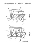
[0012]FIG. 1 is a perspective view of the present invention before pictures are inserted.
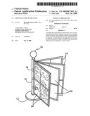
[0013]FIG. 2 displays the present invention in perspective view with some photos inserted for viewing.
[0014]FIG. 3 provides a perspective view of an alternative embodiment of the present invention as a free-standing floor unit.
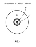
[0015]FIG. 4 is a plan sectional view from near the top showing the battery power option.
DETAILED DESCRIPTION OF A PRESENTLY PREFERRED AND VARIOUS ALTERNATIVE EMBODIMENTS OF THE INVENTION
[0016]Prior to proceeding to the more detailed description of the present invention it should be noted that, for the sake of clarity and understanding, identical components which have identical functions have been identified with identical reference numerals throughout the several views illustrated in the drawing figures.
[0017]Referring initially to FIG. 1, the present invention 10 is shown in a perspective view. A base 12 with a flat bottom is attached to the bottom end of a support post 14. The post 14 can be positioned off center to aid in counterbalancing the weight of the frames 18. Multiple picture frames 18 are aligned with one edge adjacent and parallel to the support post 14. An attachment device 17 holds the edge of frames 18 to the support post 14 in a hinged or movable manner such that the frames can be swung to various positions for viewing. This can be done in one of several ways, such as hinges or hooks attached to the frames and connecting with slots in the post. Another is having one or more straps around the circumference of the post and holding one edge of the frames against the post in a movable manner. A preferably optional lamp 16 sits atop the post 14. It can be powered by standard AC current 30 or batteries inside the post 14. An on-off switch 32 can be located in the base 12, the post 14, or just below the light 16 as shown.
[0018]FIG. 2 illustrates the present invention in a primary use, that of displaying numerous photographs 24. The support post 14 is secured vertically from base 12. Although shown at the center of base 12, the post 14 can be positioned off center to aid in counterbalancing the weight of the frames 18. The base 12 can also be weighted to offset any tendency to tip over. Multiple frames 18 are movably attached to the support post 14 with straps 19. With slots or removable backs, each frame can accept a few photos 24, and the orientation can be varied from one frame 18 to another. Those pictures labeled 24 are in portrait mode, but those at positions 26 are of landscape type wherein the width is greater than the height. This distinguishes the present invention from others which rotate frames into view only one or two at a time. In the prior art cases, the frames hold one photo each, and no allowance is made for some being in portrait orientation and others being landscape. Within each frame 18, there are preferably photos back to back so that viewing can be done from either side of frames 18. An option is to protect the photos with a transparent covering, such as glass or a clear plastic.
[0019]FIG. 3 illustrates an alternative embodiment of the present invention in the taller form of a floor lamp. In FIG. 3a, a base 12 supports a tall post 15. Although shown at the center of base 12, the post 15 can be positioned off center to aid in counterbalancing the weight of the frames 18. The frames 18 are movably held to the post 15 with attachment devices 17, in this case, hooks extending from the edge of frames 18 and engaging with a plurality of slots in the upper zone of the post 15. No limitation to this type of attachment is implied. FIG. 3b details how the hook 30 engages with the slot 32.
[0020]FIG. 4 illustrates the battery power option in a plan sectional view from near the top. Inside the support post 14 is at least one battery 36, typically with the positive terminal 38 facing up. The bottom of post 14 is attached to the base 12.
[0021]While a presently preferred and various alternative embodiments of the present invention have been described in sufficient detail above to enable a person skilled in the relevant art to make and use the same, it should be obvious that various other adaptations and modifications can be envisioned by those persons skilled in such art without departing from either the spirit of the invention or the scope of the appended claims.
User Contributions:
comments("1"); ?> comment_form("1"); ?>Inventors list |
Agents list |
Assignees list |
List by place |
Classification tree browser |
Top 100 Inventors |
Top 100 Agents |
Top 100 Assignees |
Usenet FAQ Index |
Documents |
Other FAQs |
User Contributions:
Comment about this patent or add new information about this topic:
Images included with this patent application:
 |  |
 |  |
| Similar patent applications: | |
| Date | Title |
|---|---|
| 2010-02-25 | Relating to picture frames |
| 2009-06-11 | Scented picture frame |
| 2010-01-28 | Picture frame drawing pad |
| 2012-01-26 | Flexible picture frame |
| 2010-10-07 | Chronological picture frame |
| New patent applications in this class: | |
| Date | Title |
|---|---|
| 2014-06-05 | Self-leveling mounting device for mountable objects |
| 2013-04-25 | Picture frame, method and system for attaching a picture frame to a wall surface |
| 2011-06-16 | Rotational panel assembly |
| 2008-10-02 | Autorotative digital photo frame |
| Top Inventors for class "Card, picture, or sign exhibiting" | |
| Rank | Inventor's name |
|---|---|
| 1 | David Mayer |
| 2 | Tiger Qiao |
| 3 | Jerry Guo |
| 4 | Sidney Rose |
| 5 | Allison Marsh |