Patent application title: Adjusting Structure for use in Reclining Chairs
Inventors:
Yun-Ying Kuo (Taipei City, TW)
IPC8 Class: AA47C1032FI
USPC Class:
2973003
Class name: Back and seat adjust simultaneously back tilts while seat inclination adjusts fluid-spring
Publication date: 2009-03-12
Patent application number: 20090066133
Inventors list |
Agents list |
Assignees list |
List by place |
Classification tree browser |
Top 100 Inventors |
Top 100 Agents |
Top 100 Assignees |
Usenet FAQ Index |
Documents |
Other FAQs |
Patent application title: Adjusting Structure for use in Reclining Chairs
Inventors:
Yun-Ying Kuo
Agents:
KAMRATH & ASSOCIATES P.A.
Assignees:
Origin: GOLDEN VALLEY, MN US
IPC8 Class: AA47C1032FI
USPC Class:
2973003
Abstract:
An adjusting structure for use in reclining chairs includes a reclining
chair including a seat, a chairback, two armrests, a pad and a frame. The
frame includes a hydraulic cylinder pivotally disposed on the rear end
thereof and two double rodded holders couplingly mounted on two sides
thereof respectively. The front ends of the double rodded holders and two
swinging members beneath the seat are pivotally connected with a shaft.
Each of the double rodded holders includes an offset member affixed on
the front end thereof and extending backwardly for coupling with the
bottom of the armrest. Also, the pad includes two connecting rods
attached on two sides thereof, each connecting rod having two supports
secured on the seat and the armrest respectively. The rear sides of the
two supports are coupled with the chairback by using a T-shaped piece,
thereby enabling the functions of recumbency and force-saving leave from
the reclining chair.Claims:
1. An adjusting structure for use in reclining chairs comprising:a
reclining chair including a seat, a chairback, two armrests, a pad, and a
frame, wherein said frame includes a hydraulic cylinder pivotally
disposed on a rear end of the frame, wherein said frame further includes
two double rodded holders couplingly mounted on two sides of the frame
respectively, wherein said frame further includes two swinging members
beneath said seat, wherein said frame includes a first bar extending
between front ends of said double rodded holders and a second bar
extending between the two swinging members, wherein the frame includes a
U-shaped bracket, with the first and second bars being secured in a non
movable manner in a spaced, parallel relation to the U-shaped bracket,
with the hydraulic cylinder pivotally mounted to the U-shaped bracket,
and wherein each of said double rodded holders includes an offset member
affixed on the front end thereof and extending backwardly for coupling
with a bottom of said armrest; wherein said pad includes two connecting
rods attached on two sides of the pad, with each connecting rod having
two supports secured on said seat and said armrest respectively, with
rear sides of said two supports coupling with said chairback by using a
T-shaped piece, such that as said hydraulic cylinder retracts backward
during operation, said armrests displace downwardly with the downward
swing of said offset members and said seat is pulled backward; wherein
when said chairback moves backwardly by way of the swinging of said
T-shaped pieces, the distance between said two supports expands to push
said connecting rod outwardly and said pad rotatably swings upward to
achieve complete expansion of said reclining chair for the user's
recumbency; wherein when desiring to return to a sitable mode of said
reclining chair, said hydraulic cylinder extends to actuate the forward
movement of said seat and the upward swinging of said armrests, such that
said seatback rotates angularly to become in a sitable state, and said
pad urges said connecting rods to retract by using the distance between
said two supports.Description:
BACKGROUND OF THE INVENTION
[0001]1. Field of the Invention
[0002]The present invention relates to an adjusting structure, and more particularly to an adjusting structure for use in reclining chairs that the user allows to reduce his movements and force as leaving the seat.
[0003]2. Description of the Prior Arts
[0004]Generally speaking, a reclining chair is provided to have a comfortable and relax recumbency for users, such as the elder.
[0005]For example, a prior art reclining chair always emphasizes its comfort and convenient recumbency function, however, the auxiliary function, e.g., how to leave the seat and then stand up on the ground easily is always neglected. Especially for the older user, they often act slowly and have a poor sense of balance, therefore how to design a reclining chair with comfort recumbency and easy seat-leaving function is an important challenge in the related field.
[0006]The present invention has arisen to mitigate and/or obviate the afore-described disadvantages.
SUMMARY OF THE INVENTION
[0007]The primary object of the present invention is to provide an adjusting structure for use in reclining chairs that the user allows to reduce his movements and force as leaving the seat.
[0008]Another object of the present invention is to provide an adjusting structure for use in reclining chairs that the elder who acts slowly may use the reclining chair safely.
[0009]In accordance with one aspect of the present invention, there is provided an adjusting structure for use in reclining chairs comprising a reclining chair including a seat, a chairback, two armrests, a pad and a frame, wherein the frame includes a hydraulic cylinder axially disposed on the rear end thereof, and includes two double rodded holders couplingly mounted on two sides thereof respectively, and the front ends of the double rodded holders and two swinging members beneath the seat axially connect with a shaft individually, and each of the double rodded holders includes an offset member affixed on the front end thereof and extending backward for coupling with the bottom of the armrest. Besides, the pad includes two connecting rods attached on two sides thereof individually, and each having two supports secured on the seat and the armrest respectively, the rear sides of the two supports couple with the chairback by using a T-shaped piece, hence as the shaft retracts backward during operation, the armrests displace downwardly with the downward swings of the offset members (the front ends of the double rodded holders swing upward and downward with the extension and the retraction of the shaft), and the seat is pulled backward (due to the retraction of the shaft, the swinging members generate a backward pulling force relative to the seat); in the meantime, the chairback moves backwardly by way of the swings of the T-shaped pieces, and the distance between the two supports expands for pushing the connecting rod outwardly, accordingly the pad rotatably swings upward to achieve the complete expansion of the reclining chair for user's recumbency
[0010]On the contrary, while desiring to return the sitable mode of the reclining chair, the shaft is pushed to actuate the forward movement of the seat and the upward swings of the armrests, therefore the seatback rotates angularly to become a sitable state, and the pad urges the connecting rods to retract by using the distance between the two supports, thus returning a sitable mode of the reclining chair.
[0011]On the other hand, during the shaft of the hydraulic cylinder extends up to its longest travel, since the front ends of the double rodded holders axially connect with the shaft, they are lifted upwardly with the extension of the shaft and rotatably inclined forward, thus the armrests become a raised and forward inclined state. During this process, because the seat, the seatback and the armrests couple with each other by means of the supports and the T-shaped pieces, and the swing members of the seat connect with the shaft as well, the seat and the seatback are simultaneously raised upwardly and then become inclined forwardly with the movement of the armrests, causing an upward raised and forward inclined state of the reclining chair. Thereby, the user allows to reduce his movements and force by straightly stepping from the seat and standing up on the ground. Likewise, the reclining chair may be served to the elder who acts slowly.
[0012]The present invention will become more obvious from the following description when taken in connection with the accompanying drawings, which show, for purpose of illustrations only, the preferred embodiment in accordance with the present invention.
BRIEF DESCRIPTION OF THE DRAWINGS
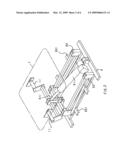
[0013]FIG. 1 is a perspective diagram illustrating the assembly of a reclining chair according to the present invention;
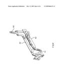
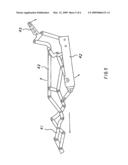
[0014]FIG. 2 is a perspective diagram illustrating the exploded components of a base according to the present invention;
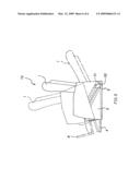
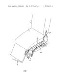
[0015]FIG. 3 is a perspective diagram illustrating a connecting rod being attached onto the reclining chair according to the present invention;
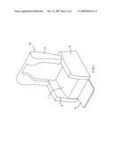
[0016]FIG. 4 is a perspective diagram illustrating the assembly of the connecting rod according to the present invention;
[0017]FIG. 5 is a plane diagram illustrating the operation of the connecting rod according to the present invention;
[0018]FIG. 6 is a plane diagram illustrating the operation of an adjusting structure for use in reclining chairs according to the present invention.
DETAILED DESCRIPTION OF THE PREFERRED EMBODIMENT
[0019]An adjusting structure for use in reclining chairs in accordance with the present invention comprises a reclining chair 10 including a seat 1, a chairback 2, two armrests 3, a pad 4 and a frame 5 as illustrated in FIG. 1, wherein the frame 5 includes a hydraulic cylinder 51 axially disposed on the rear end thereof and includes two double rodded holders 52 couplingly mounted on two sides thereof respectively as shown in FIG. 2, and the front ends of the double rodded holders 52 and two swinging members 11 beneath the seat 1 axially connect with a shaft 511 individually, each of the double rodded holders 52 includes an offset member 521 affixed on the front end thereof and extending backward for coupling with the bottom of the armrest 3. Besides, the pad 4 includes two connecting rods 41 attached on two sides thereof individually as illustrated in FIGS. 3 and 4, and each having two supports 42 secured on the seat 1 and the armrest 3 respectively, and the rear sides of the two supports 42 couple with the chairback 2 by using a T-shaped piece 43, hence as the shaft 511 retracts backwardly during operation, the armrests 3 displaces downwardly with the downward swings of the offset members 521 (the front ends of the double rodded holders 52 swing upward and downward with the extension and the retraction of the shaft 511), and the seat 1 is pulled backward (due to the retraction of the shaft 511, the swinging members 11 generate a backward pulling force relative to the seat 1); in the meantime, the chairback 2 moves backwardly by way of the swings of the T-shaped pieces 43, and the distance between the two supports 42 expands to push the connecting rod 41 outwardly (as shown in FIG. 5, the present invention is utilized the expansion of the two supports 42 to control the extension and the extraction of the connecting rod 41), accordingly the pad 4 rotatably swings upward to achieve the complete expansion of the reclining chair 10 for user's recumbency as shown in FIG. 6.
[0020]On the contrary, while desiring to return the sitable mode of the reclining chair 10, the shaft 511 is pushed to actuate the forward movement of the seat 1 and the upward swings of the armrests 3, therefore the seatback 2 rotates angularly to become a sitable state, and the pad 4 urges the connecting rods 41 to retract by using the distance between the two supports 42, thus returning a sitable mode of the reclining chair 10.
[0021]On the other hand, during the shaft 511 of the hydraulic cylinder 51 extends up to its longest travel, since the front ends of the double rodded holders 52 axially connect with the shaft 511, they are lifted upwardly with the extension of the shaft 511 and rotatably inclined forward, thus the armrests 3 become a raised and forward inclined state. During this process, because the seat 1, the seatback 2 and the armrests 3 couple with each other by means of the supports 42 and the T-shaped pieces 43, and the swing members 11 of the seat 1 connect with the shaft 511 as well, the seat 1 and the seatback 2 are simultaneously raised upwardly and then become inclined forwardly with the movement of the armrests 3, causing an upward raised and forward inclined state of the reclining chair 10. Thereby, the user allows to reduce his movements and force by straightly stepping from the seat and standing up on the ground. Likewise, the reclining chair 10 may be served to the elder who acts slowly.
[0022]The invention is not limited to the above embodiment but various modifications thereof may be made. It will be understood by those skilled in the art that various changes in form and detail may made without departing from the scope and spirit of the present invention.
User Contributions:
comments("1"); ?> comment_form("1"); ?>Inventors list |
Agents list |
Assignees list |
List by place |
Classification tree browser |
Top 100 Inventors |
Top 100 Agents |
Top 100 Assignees |
Usenet FAQ Index |
Documents |
Other FAQs |
User Contributions:
Comment about this patent or add new information about this topic:
Images included with this patent application:
 |  |
 |  |
 |  |
 |
| Similar patent applications: | |
| Date | Title |
|---|---|
| 2012-07-12 | Adjustment structure for chair armrest |
| 2012-12-13 | Stretching structure of chair upholstery material |
| 2013-02-07 | Connecting rod and double reclining mechanism |
| 2009-08-06 | Rotating structure for armrests |
| 2010-05-13 | Structure for connecting members |
| New patent applications in this class: | |
| Date | Title |
|---|---|
| 2014-02-20 | Modular chair mechanism with self-weighing |
| 2010-09-30 | Chair providing more comfortable when seated in optimum posture while reclining |
| Top Inventors for class "Chairs and seats" | |
| Rank | Inventor's name |
|---|---|
| 1 | Johnathan Andrew Line |
| 2 | Larry P. Lapointe |
| 3 | Yukifumi Yamada |
| 4 | John W. Jaranson |
| 5 | Arjun Yetukuri |