Patent application title: Multi-Purpose Waterproof Case
Inventors:
Helen May Ling Leung (Hong Kong, HK)
Assignees:
Macer Limited
IPC8 Class: AB65D8538FI
USPC Class:
2063162
Class name: Special receptacle or package for an optical device or element (e.g., camera, telescope, binoculars, microscope, lens, filter, etc.) camera
Publication date: 2009-03-05
Patent application number: 20090057181
Inventors list |
Agents list |
Assignees list |
List by place |
Classification tree browser |
Top 100 Inventors |
Top 100 Agents |
Top 100 Assignees |
Usenet FAQ Index |
Documents |
Other FAQs |
Patent application title: Multi-Purpose Waterproof Case
Inventors:
Helen May Ling Leung
Agents:
Ben Kwong;Rm404, 4/F.
Assignees:
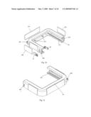
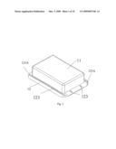
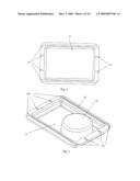
Macer Limited
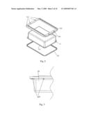
Origin: HONG KONG, HK
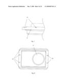
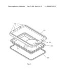
IPC8 Class: AB65D8538FI
USPC Class:
2063162
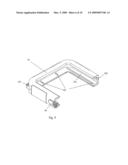
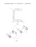
Abstract:
An air-tight polygonal, resembling a rectangular shape of, container for
accommodating camera for underwater use. The airtight container consists
of a casing and a lid, sealing by a pair of clamps together with a pair
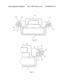
of clamping device each (part) with an about horizontal groove on the
inner surface of the clamping device for the casing and lid to slide into
the brackets to tight-fit easily. Both the casing and the lid do not
stand alone, but form with integral parts to form the casing compartment
and the lid section. On each of the casing compartment and the lid
section are two slots on each of the width-long sides. The slots will
tight-fit with the locking projections in the inner bottom of the
clamping device, also with two locking projections on each of the
width-long side. The sealing effect of this new invention is further
guaranteed by the use of a flange on each of the length-long side so that
the container is sealed and will not be fallen apart because of external
forces.Claims:
1. A sealed container which is characterized with and consisted of:An
openable lid hinged to a casing compartment, on which there are edges on
both the lid and the casing compartment forming the edge of the container
when the container is closed and sealed.A clamping device formed from two
brackets, each with a pair of flanges and their corresponding grooves
which extend from one flange and go around bracket. Each of the bracket
takes up half of the perimeter of the upper rim of the container.
2. The sealed container as defined in claim one wherein said is with a polygonal casing, resembling very much a rectangular shape, and its corresponding lid.
3. The claimed edges as defined in claim one wherein said are quadruple in shape with all four sizes equal and are hinged outwardly along the bottom periphery of the lid and along the upper rim of the casing so to form the edge of the container when closed for sealing effect.
4. The claimed casing and lid as defined in claim two wherein said have two slots on the width-long side each.
5. The clamping device as defined in claim one wherein said is a combination of:A pair of brackets with about horizontal grooves slideably tight-fit with the length-long slots of the casing and the lid to form a sealing effect.On both end of the brackets are a pair of flanges tight-fit into a G-shape groove to form a locking device.
6. The claimed pair of clamping brackets defined in claim four wherein said is nearly identical except on one end is a pair of flanges, each on the length-long side; and on the other end are the G-shape grooves where the flange on each of the length-long side tightly fit to lock up the two brackets together so they will not fallen apart.
7. The claimed pair of clamping brackets defined in claim four wherein said have two projections on each of the width-long side, which match with the slots on the width-long sides of the lid and the casing to lock up the casing and the lid and form a sealing effect.
8. The claimed pair of claiming brackets defined in claim four wherein said has two holes hinged from the opposite corner of each bracket for neck straps or lanyards for easy hand-held in and outside water.
Description:
BACKGROUND OF THE INVENTION
[0001]1. Field of the Invention
[0002]The present invention pertains to an air-tight container, and more particularly, to those for housing a camera and to be used underwater.
[0003]2. Prior Art
[0004]Waterproof container in prior art has the following structure: a rectangular case and a lid of the same shape. Between the lid and the case is an o-ring, a rubber ring used as a gasket. However, the sealing effect of this kind of waterproof container is not good as the o-ring slips off easily. There is another type of sealed container in prior art which consists of a rectangular case and a lid of the same shape. On the case and the lid are grooves. On one side the groove is concave in shape while on the other side the groove is convex. By applying external forces and pressure, the grooves will fit tightly and form a seal. However, the defect of this design is that the hardening of the materials of the container will cause deformation on the grooves and hence the seal is not tight. In addition, excess forces or over pressure on the container or on the lid will cause the lid to fall out from the case. In some situations, for example in the water, it will lead to serious outcomes like the flooding into the container.
SUMMARY OF THE INVENTION
[0005]The sealed container of the present invention aims to provide a reliable air-tight device for accommodating camera underwater without the worry of the misplacement of the gasket or the deformation of air-tight device causing by the deterioration of materials. The reliability of the present invention lies further on the elimination of accidental destruction of the air-tight condition of the container because of the inapplicable exertion of external forces.
[0006]To accomplish the above-mentioned goals, the present invention of the sealed container consists of a container and a pair of clamping brackets.
[0007]The container comprises of a casing and the assembled lid, which both are formed with integral parts. The container has itself edges formed from the edges of the casing and the lid to form the sealing effect. The edges of the container are quadruple in shape with four equal sides. And there are two slots on each of the width-long sides to sit tightly into the locking projections of the clamping brackets.
[0008]The casing comprises of the container compartment and a pair of assembled skirts. The container compartment is a polygonal container with a bottom and four walls, resembling very much rectangular in shape. The pair of skirts creates the edge for the casing and is structured with hooks to integrate with the clamping brackets as well as two slots on each of the width-long side to lock up the projection locks in the clamping brackets. The lower skirt is of the same width of the periphery of the container compartment whereas the upper skirt is hinged outward from the width of the periphery of the container compartment. The container compartment is put between the skirts.
[0009]The lid comprises of the lid compartment and a pair of skirts. The lid compartment is identical with the container compartment, except its bottom is not flat, but protruding inward to accommodate the lens of the camera. The pair of skirts creates the edge for the lid and is structured with hooks to integrate with the clamping brackets as well as two slots on each of the width-long side to lock up the projection locks in the clamping brackets. The lower skirt is of the same width of the periphery of the lid compartment whereas the upper skirt is hinged outward from the width of the periphery of the lid compartment. The lid compartment is put between the skirts. Despite the materials to be used for the sealed container, the top of the protruding part to accommodate the lens of the camera must be of materials offering high quality transparency.
[0010]The pair of clamping brackets in fact comes in two parts. Each part is of the same length, making up the perimeter of the rim of the container. There is an about horizontal groove which enables the periphery of the container slides in smoothly and tightly. On one end of the bracket is a pair of flanges, one of each side of the length-long side; on the other end of the bracket is a G-shape groove where the pair of flanges tightly fit to lock up the two brackets together so they will not fallen apart. In the inside bottom of each bracket are two locking projections on the width-long side, which inter-lock with the two slots on each width-long sides of the casing and the lid. In the brackets there are also two grooves on the length-long side to inter-lock with the length-long slots at the hinges of the casing and the lid.
BRIEF DESCRIPTION OF THE DRAWINGS
[0011]Diagram 1 is the structure stereogram of the sealed container
[0012]Diagram 2 is the schematic perspective view showing the casing of the sealed container from the bottom
[0013]Diagram 3 is the side view of Diagram 1.
[0014]Diagram 4 is the aerial view of the Diagram 1.
[0015]Diagram 5 is the structure stereogram of a sealed container from the top.
[0016]Diagram 6 is the schematic perspective view showing the sealed container from the top.
[0017]Diagram 7 is the side view of Diagram 5.
[0018]Diagram 8 is the aerial view of the Diagram 5.
[0019]Diagram 9 is the structure stereogram of the first part of the clamping device showing the grooves, the slot, the flange and the hole for attaching strings
[0020]Diagram 10 is the exploded diagram of the first part of the clamping device.
[0021]Diagram 11 is the structure stereogram of the second part of the clamping device.
[0022]Diagram 12 is the top view of Diagram 9.
[0023]Diagram 13 is the exploded diagram of the flanges 60 in Diagram 9.
[0024]Diagram 14 is the schematic view of the flanges after assembly.
[0025]Diagram 15 is the schematic view showing the casing, the lid and the clamping device of a preferred embodiment of a sealed container for accommodating camera.
[0026]Diagram 16 is the cross-sectional view through the sealed container from the width-length to show the sealed container with a camera put inside and the flanges closed.
[0027]Diagram 17 is the enlarged view of the cross-sectional view of the clamping brackets in Diagram 16.
DESCRIPTION OF THE PREFERRED EMBODIMENTS
[0028]Diagram 1 depicts the bottom view of the container. As shown in Diagram 2, the casing of the container comprises of three parts: the container compartment 11 with the periphery 111, the lower skirt 121 and the upper skirt 122. On the upper skirt 122 are two slots 223 on each of the width-long sides and two length-long slots at the hinges of the corners of the width-long sides. The container compartment 11 is a polygonal container with rounded corners and an extended periphery 111 extending horizontally from the rim of the container compartment 11.
[0029]Diagram 3 shows the side view of the assembled casing 10 with the view of the length-long slot at the hinge of the corner of a width-long side and another small rectangular slot on the width-long side. Diagram 4 is the aerial view of the casing 10 as per looking into the container compartment 11. Two length-long slots 123 at the hinges of the corners of each of the width-long sides are shown clearly.
[0030]Diagram 5 shows the aerial view of the lid part. It can be seen that there is an inwardly protruding part 23 from the bottom of the lid compartment 21. On the assembled lid skirt 22 are four slots 223 on each of the width-long side, among which are the two length-long slots 223 at the hinges from the corners of the width-long sides. As depicted in Diagram 6, the lid compartment actually comprises three parts: the lower skirt 222, the lid compartment 21 with periphery 211, and the upper skirt 221 with slots 223. The lid part is also polygonal in shape with round corners and an extended periphery 211 extending horizontally from the rim of the lid compartment 21.
[0031]Diagram 7 shows the side view of the assembled lid with the view of the cross-sectional view of the length-long slot 223 on the hinge at the corner of the width-long side and the slot 223 on the width-long side skirts 22. The inwardly protruding part 23 can be seen is higher than the wall of the lid compartment.
[0032]Diagram 8 is the aerial view of the lid. Two slots 223 on each of the width-long side with and the inwardly protruding part 23, and the two length-long slots 223 at the hinges from the corners of the width-long sides are shown.
[0033]Each of the pairing clamping brackets is identical. Diagram 9 shows that at one end of the bracket is the flange 60, with a hole 307 hinged at the corner on the same side as the flange 60 for neck straps or lanyards. At the other end of the clamping bracket is the g-shape groove 305 to hold the flange from the other bracket so to lock up the brackets together so they will not fall apart. Inside the bracket are two slots 302 on the width long side and the grooves 301 on the length-long side. Diagram 10 shows the hand-grip 306 used along the side of the bracket to prohibit slipping. The flange 60 in Diagram 9 is made up of two parts, 61 and 62. The two parts of the flange assembled through the hole 304 on the bracket 30, with the two slots 332 on the width-long side and the groove 31 on the length-long side.
[0034]Diagram 11 is also the view of a bracket. It is identical as Diagram 9 except in different direction. In Diagram 11, the G-shaped groove 405 which is identical to the G-shape groove 305, except it is on the left hand-side of the diagram. The hole 407 is hinged at the corner on the same length-long side with the unseen flange. The groove 402 and the groove 301 in Diagram 9 are to be interlocking with the length-long slots in the casing and the lid as depicted in Diagram 2-8.
[0035]Diagram 12 is the aerial view of Diagram 11, of which the said unseen flange 404 can be seen and the hole 407 can be seen clearly hinged at the corner on the same length-long side of the flange. 406 is the hand-grip.
[0036]Diagram 13 shows the assembly of the pair of flanges. The tenon 611 of the flange part 61 is designed to tight-fit the mortise 621 of the flange part 62, hook 622 of the flange part 62 is to be rotated into the upright part of the L-shaped groove, and the tab 612 should match with the bottom of the hook 622 in the L-shaped groove so as to keep the hook 622 in place, as depicted in Diagram 14.
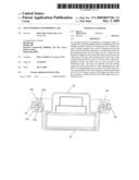
[0037]Diagram 15 shows the assembly of the sealed container, with the camera 100 put inside the casing 10 and put on the lid 20, whereas the clamping bracket 30 and the clamping bracket 40 to be incorporating from the side in opposite direction, so the edge of the casing and the lid slides into the grooves 305 and 402, and the projection locks 302 inter-locking with the slots 223, and eventually close and form the sealed container by closing the flange 60.
[0038]Diagram 16 and 17 are the cross-sectional views through the width-long side. On the bottom is the casing 10 covering by the lid part 20. This side view shows clearly how the slots 224 and 124 inter-lock with the projection locks 302 and 303 to form the sealed container with the flange 60.
User Contributions:
comments("1"); ?> comment_form("1"); ?>Inventors list |
Agents list |
Assignees list |
List by place |
Classification tree browser |
Top 100 Inventors |
Top 100 Agents |
Top 100 Assignees |
Usenet FAQ Index |
Documents |
Other FAQs |
User Contributions:
Comment about this patent or add new information about this topic:
Images included with this patent application:
 |  |
 |  |
 |  |
 |  |
 |  |
 |
| Similar patent applications: | |
| Date | Title |
|---|---|
| 2011-02-03 | Multi purpose personal protection equipment kit |
| 2011-09-15 | Multi-purpose merchandise tray |
| 2011-09-15 | Multi-purpose merchandise tray |
| 2011-08-25 | Multipurpose ipad case |
| 2008-12-18 | Multi-purpose golf bag |
| New patent applications in this class: | |
| Date | Title |
|---|---|
| 2017-08-17 | Mounting apparatus for light socket |
| 2015-12-10 | Camera and accessory carrying case with improved protection and access features |
| 2015-11-19 | Packaging box of egg-shaped apparatus |
| 2015-02-26 | Divider system for a camera bag |
| 2013-11-07 | Carrier for photographic equipment such as cameras and lenses |
| Top Inventors for class "Special receptacle or package" | |
| Rank | Inventor's name |
|---|---|
| 1 | Donald E. Weder |
| 2 | Brett R. Glass |
| 3 | Daniel Lee Bizzell |
| 4 | Andrea Biondi |
| 5 | Nicole E. Glass |