Patent application title: Shingle Separator Tool
Inventors:
Ward H. Moore (Colorado Springs, CO, US)
IPC8 Class: AE04D1502FI
USPC Class:
81 45
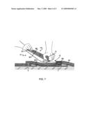
Class name: Tools shingle tool
Publication date: 2009-03-05
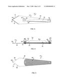
Patent application number: 20090056505
Inventors list |
Agents list |
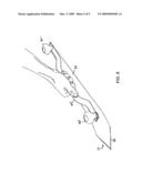
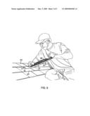
Assignees list |
List by place |
Classification tree browser |
Top 100 Inventors |
Top 100 Agents |
Top 100 Assignees |
Usenet FAQ Index |
Documents |
Other FAQs |
Patent application title: Shingle Separator Tool
Inventors:
Ward H. Moore
Agents:
HANES & SCHUTZ, LLC
Assignees:
Origin: COLORADO SPRINGS, CO US
IPC8 Class: AE04D1502FI
USPC Class:
81 45
Abstract:
A shingle separator tool for slicing through the adhesive strips or spot
welds that hold overlapping roof or side wall shingles in place against
the force of wind comprising a rigid elongated body having distal and
proximal ends and a pair of spaced apart gripping handles. A flexible
blade disposed forwardly of the body and which is either attached to the
distal end of the body or which is integral with the body includes a
flexible end portion having sharpened edges that are angularly disposed
with respect to one another and which define a point at the apex of the
intersecting edges.Claims:
1. A shingle separator tool comprising,an elongated flexible blade having
lateral sides, top and bottom surfaces, a longitudinal axis and distal
and proximal ends, where the distal end comprises sharpened opposing
sides that intersect the lateral sides and which are angularly disposed
with respect to the longitudinal axis, defining a point at the
intersection of the sharpened edges, andhandle means attached to the
blade and disposed over the top surface of the blade for providing a grip
on the separator.
2. The shingle separator of claim 1 and further including stiffener means having proximate and distal ends and disposed over the top surface of the flexible blade and attached to the blade at its proximal and distal ends for stiffening that portion of the blade that is beneath the stiffener means.
3. The shingle separator of claim 1 and further including a pad attached to the bottom surface of the blade where the pad has a higher coefficient of friction than the bottom surface of the blade.
4. The shingle separator of claim 2 where the stiffener means comprises an elongated member that is disposed over the longitudinal axis of the blade and where the proximal end is congruent with the proximal end of the blade and the distal end is positioned proximal to the sharpened edges of the distal end of the blade.
5. The shingle separator of claim 4 where the handle means includes forward and rearward spaced apart knobs each to be grasped by a hand and respectively disposed at the distal and proximal ends of the stiffener means.
6. The shingle separator of claim 5 and further including congruent bolt retaining adjustment slots in the blade and the forward end of the stiffening means and a threaded bolt disposed in said slots that is threaded into the forward knob handle.
7. The shingle separator of claim 1 where the lateral sides of the flexible blade taper from their intersection with the sharpened edges toward the proximal end of the blade.
8. A shingle separator tool comprising,an elongated body having distal and proximal ends and a pair of spaced apart gripping handles,a flexible blade carried by the distal end of the body and having sharpened edges that are angularly disposed with respect to one another and which define a point at the apex of the intersecting edges.
9. The shingle separator of claim 8 where the body includes a bottom portion comprising an extension of the flexible blade.
10. The shingle separator of claim 9 and further including,a pad fixed to the bottom portion of the body where the pad has a greater coefficient of friction than the coefficient of friction of the extended flexible blade.
Description:
FIELD OF THE INVENTION
[0001]The present invention relates to a tool for separating composition roofing shingles or similar layered articles that are adhered together through a gluing process or have become fused together through heat.
BACKGROUND OF THE INVENTION
[0002]The thin pieces of building material laid in overlapping rows as a covering for the roof or sides of a building, known as composition shingles, have evolved over the years. From being units that are primarily nailed to an underlying frame structure, and to one another, shingles are now designed to withstand separation from the force of wind by being glued or fused together where they overlap. In the earlier days of adhesive connection a simple ribbon of asphalt that melted on a hot day would stick the shingles together. Breaking the asphalt tie was reasonably easily done in cool weather or after treating the shingles with ice water to make the asphalt brittle and easier to break. However, modern synthetic adhesives have made the separation process substantially more difficult when it becomes necessary to repair a roof and remove a number of shingles without causing damage to those being removed and to the remaining adjacent shingles.
[0003]Although the adhesion method produces a superior product from the standpoint of surviving wind damage, it creates substantial difficulties for the technician who is called on to repair a section of such a roof or to remove a section of shingles to make room for a skylight or other appliance. In resisting an attempt to pull adhered shingles apart they may tear. Using a pry bar or similar leverage tool will cause pieces or strips of the shingle to be pulled out, making it unfit for further use. Work intended for a small section of roof can quickly escalate into major shingle replacement, to say nothing of the extreme effort and time consumed in separating the shingles that are the object of the job.
[0004]It is therefore the primary object of the present invention to provide a tool that can be manipulated by a single workman and which can separate adhered shingles without damaging the shingles being separated.
SUMMARY OF THE INVENTION
[0005]The shingle separator tool of the present invention comprises an elongated flexible thin blade having distal and proximal ends, where the distal end comprises sharpened opposing sides that are angularly disposed with respect to one another and which define a point at the intersection of the sharpened edges. The flexible nature of the blade enables the operator of the tool to hold the body of the tool at an angle to the plane of the shingles while the pointed knife edges at the tip of the blade are inserted between the shingles and function on the same plane in which the shingles lie. In order to make the flexible blade stiff and rigid over the portions thereof that are gripped by the operator, a stiffening spine is disposed over the top surface of the flexible blade. Gripping handles are attached to the blade, preferably at each end of the spine.
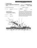
DESCRIPTION OF THE DRAWINGS
[0006]FIG. 1 is a perspective view of adhered shingles being pulled or pried apart by prior art methods with specific illustration of the destruction of the shingles when parts of the adhesive layer are pulled out of the shingle.
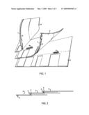
[0007]FIG. 2 is a diagrammatic cross section of three rows of shingles showing the line of adhesive that keeps the layers of shingles together in high wind conditions.
[0008]FIG. 3 is a top view of the shingle separator tool of the present invention.
[0009]FIG. 4 is a side view of the tool.
[0010]FIG. 5 is a bottom view of the tool.
[0011]FIG. 6 is an illustration of a workman using the tool of the present invention to separate shingles.
[0012]FIG. 7 is a fragmentary cross sectional view of overlapping rows of shingles showing a fused adhesion that is being separated by the forward knife edges of the tool of the present invention. The operator of the tool is shown fragmentarily gripping the spaced apart handles of the tool.
[0013]FIG. 8 is a perspective view of an alternative handle for the tool.
DETAILED DESCRIPTION OF PREFERRED EMBODIMENT
[0014]As discussed above, pulling or prying apart the adhered shingles of FIG. 2 with tools of the prior art such as pry bars, claws or the like results in either tearing or pulling plugs out of the shingles, as illustrated in FIG. 1. In FIGS. 1 and 2 three rows of laminate composition shingles 2, 3 and 4 are shown. A line of adhesive 5 is used to stick the exposed edge 7 of the upper row of shingles to the body portion of the lower row of shingles. In FIG. 1 the second and third rows 3 and 4 are folded back to illustrate the plugs 8 and 9 that have been torn from the shingles when they are pried or pulled apart because currently used adhesives are stronger than the shingle itself.
[0015]The separator tool 10 of the present invention presents a solution to the problem addressed above. A flexible bodied cutting instrument 12 is formed on or carried by the distal end of a body 14 having one or more handles with which a workman may manipulate the sharp cutting edges 25 on the distal end of the tool to slice through an adhesive layer, as shown in FIGS. 6 and 7. The cutting instrument can be a separate element that is attached to a body 14. Preferably however, the cutting instrument 12 is integral with the body portion 14, as shown in the embodiment of the tool illustrated in FIGS. 3, 4 and 5. In the illustrated embodiment the body 14 comprises an elongated blade 22 whose forward or distal end portion includes the cutting instrument 12 having sharpened edges 25 that are angularly disposed to the longitudinal axis of the body 14. The cutting edges intersect to form a point 24 that is useful for making initial entry of the blade between overlapping shingles.
[0016]The cutting portion 12 of the tool in front of or distal to a front knob handle 16f comprises a thin flexible blade that can be inserted between adhered shingles. The preferred degree of blade flex is comparable to the flex of the blade of an ordinary carpenter's hand saw. This flex is the property of the tool that allows the operator to position the body 14 of the tool at an angle to the shingles while the cutting portion 12 is positioned substantially parallel to the plane of the shingles, as illustrated in FIGS. 6 and 7. This operative positioning of the respective parts of the tool allows the operator an appropriate angle with which to apply the necessary force to the tool while the cutting portion 12 remains parallel to the plane of the shingles, thus providing maximum efficiency of the sharpened edges 25 as they are applied to cut the adhesive ribbons or spot welds that keep the shingles together.
[0017]As pointed out above, the preferred form of the invention contemplates that the cutting portion 12 and the base portion of the body 14 are formed of a unitary piece of elongated steel 22. However, such construction requires an additional stiffening component 32 in order to make the body portion rigid enough to tolerate forceful manipulation by the operator without undesired bending or flexing of the body. The stiffener of the preferred embodiment includes a flat strip 34 of rigid material such as steel and a perpendicular rib 36 integral with the flat strip. Together the strip and the rib resist bending or torsion of the elongated blade 22. The stiffening element 32 is attached at each of its ends to the blade 22 with screws or bolts 38. In addition to interconnecting the blade 22 with the stiffener 32 the bolts 38 also mount the front and rear knob handles 16 with threaded connections. The rear bolt 35 passes through a hole in the blade 22 and thus secures knob handle 16r in a fixed position. As shown in FIG. 3, the forward or distal end of the flat stiffener strip 34 and the corresponding portion of the blade 22 are provided with slots 36 through which the shank of the bolt 38 passes. When at rest, the bolt 38 assumes a position within the slots. If, in that position the handle 16f is tightened, the blade will have certain flexibility. However, if the handle 16f is unscrewed or loosened the bolt can assume different positions within the slots as different forces are applied to the tool and the blade will have greater flexibility and torsional freedom.
[0018]A spacer 40 is positioned between the bottom of the stiffener strip 34 and the elongated blade 22 to provide flex in the opposite direction to that shown in FIGS. 6 and 7 if and when needed. This allows the entire blade body 22 to flex downward without creating a horizontal line of stress in one spot perpendicular to the longitudinal axis of the tool.
[0019]As a safety feature, the bottom side of the body 14 has attached thereto a pad 45 of material, such as rubber, for example The coefficient of friction of the pad is greater that than of the bottom of the body, thus preventing the tool from sliding off of the roof when not being used by the operator.
[0020]As shown in FIGS. 6 and 7 the pointed end of the tool is first inserted between the shingles 60 and 65 to be separated. The width of that portion 12 of the blade having the sharpened cutting edges 25 allows the blade to then slice across the fused sections 68 of overlapping shingles in an angular motion whose components are perpendicular to the longitudinal axis of the body 14 and forward along its longitudinal axis.
[0021]FIG. 8 illustrates an alternative form of handle that permits a user to operate the tool with one hand when less than maximum force is required. The alternative handle 60 is tubular shaped with crimped ends that are equivalent to the flat ends of the stiffening strip 34 in regard to mounting the alternative handle 60 with the standard knob handles 16. The tubular shape of the handle 60 is rigid and doubles as a stiffening element for the main body of the blade 22.
User Contributions:
comments("1"); ?> comment_form("1"); ?>Inventors list |
Agents list |
Assignees list |
List by place |
Classification tree browser |
Top 100 Inventors |
Top 100 Agents |
Top 100 Assignees |
Usenet FAQ Index |
Documents |
Other FAQs |
User Contributions:
Comment about this patent or add new information about this topic:
Images included with this patent application:
 |  |
 |  |
 |  |
| Similar patent applications: | |
| Date | Title |
|---|---|
| 2013-05-23 | Shingle removal tool |
| 2013-10-10 | Meshing gyration tool |
| 2013-09-19 | Squeezing head torque tool |
| 2009-02-12 | Pipe extraction tool |
| 2010-02-25 | "optimized key ring separator" |
| New patent applications in this class: | |
| Date | Title |
|---|---|
| 2015-12-03 | Roofing fork |
| 2014-10-16 | Material removal tool |
| 2012-04-26 | Semi-automated shingle removal apparatus |
| 2011-08-25 | Shingle popper |
| Top Inventors for class "Tools" | |
| Rank | Inventor's name |
|---|---|
| 1 | Bobby Hu |
| 2 | Chih-Ching Hsieh |
| 3 | Ronald L. Johnson |
| 4 | Yugen Patrick Lockhart |
| 5 | Robert J. Gallegos |