Patent application title: Method And Device For Compensating The Mounting Tolerances Of A Distance Sensor
Inventors:
Norbert Höver (Lippstadt, DE)
Norbert Höver (Lippstadt, DE)
Thomas Ottenhues (Hoerstel, DE)
Assignees:
HELLA KGaA
IPC8 Class: AG01P2100FI
USPC Class:
702 94
Class name: Data processing: measuring, calibrating, or testing calibration or correction system position measurement
Publication date: 2009-02-26
Patent application number: 20090055117
Inventors list |
Agents list |
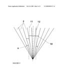
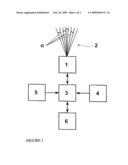
Assignees list |
List by place |
Classification tree browser |
Top 100 Inventors |
Top 100 Agents |
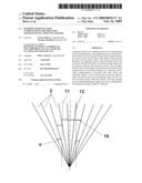
Top 100 Assignees |
Usenet FAQ Index |
Documents |
Other FAQs |
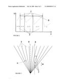
Patent application title: Method And Device For Compensating The Mounting Tolerances Of A Distance Sensor
Inventors:
Norbert Hover
Thomas Ottenhues
Agents:
HUSCH BLACKWELL SANDERS LLP
Assignees:
HELLA KGaA
Origin: ST. LOUIS, MO US
IPC8 Class: AG01P2100FI
USPC Class:
702 94
Abstract:
A distance sensor with a method and device for compensating for mounting
tolerances. Mounting tolerances may make distance sensors fail in
correctly measuring the angle between the sensor and an object which will
result in wrong lateral spacing to be computed. Sensor values therefore
need to be corrected. Available methods of correction require quite a lot
of memory capacity and processor power. The invention therefore aims at
providing a method and a device that aid the compensation of mounting
tolerances of a distance sensor, where compensation is provided with
little effort and extremely quickly. This is achieved by having the
distance sensor (1) emit its rays (2) at an aperture angle (a) of
0.1° to 10° and pick up data while the vehicle is moving
straight forward, and determining an angle error (δ) by comparing
the data picked up during a chance of channels.Claims:
1. A method of compensating the mounting tolerances of a vehicle-mounted
distance sensor, comprising:during operation, the distance sensor emits a
plurality of rays at specified angles in relation to the vehicle axis and
receives reflected rays, every ray representing one channel, where each
of the rays are emitted one by one at a cyclic clock intervals and where
channel data is analyzed and corrected as appropriate;wherein the rays
(2) are emitted at an aperture angle of 0.1.degree. to 10.degree.;data is
collected while driving straight ahead; andan angle error is computed by
comparing values measured at a time where the channels change.
2. The method as in claim 1, wherein a value consists of the coordinates of a stationary object; anda regression gradient is determined for all coordinates of the object with the angle error being the same as the angle between the regression gradient and a straight reference line.
3. The method as in claim 1, wherein a value consists of the coordinates of a stationary object; anda distance traveled between two subsequent changes of channels, an actual emitter angle is computed from the value and compared with a reference value, and the angle error is the difference between the values compared.
4. The method as in claim 1, wherein a value consists of different distances to a second vehicle driving ahead, where lateral boundaries of the second vehicle are detected, and the angle error is computed using a difference between a scanned center of the vehicle driving ahead and a center of a sensor vehicle as a basis.
5. The method as in claim 1, wherein the aperture angle of the rays is between 0.1.degree. to 5.degree..
6. The method as in claim 1, wherein the aperture angle of the rays is 1.degree..
7. A device for compensating for the mounting tolerances of a vehicle-mounted distance sensor comprising:the distance sensor emits and receives a plurality of rays at specified angles in relation to a vehicle axis, where every ray represents one channel;a control unit for actuating the sensor to emit the rays at cyclic intervals; andan analyzer for analyzing values determined by the distance sensors;wherein an aperture angle of the rays is between 0.1.degree. and 10.degree.,an element determines whether the vehicle is driving straight ahead; andthe analyzer computes an angle error by comparing the values collected as channels changed while driving straight ahead.
8. The device as in claim 7, wherein the aperture angle of the rays is between 0.1.degree. and 5.degree..
9. The device as in claim 7, wherein the aperture angle of the rays is 1.degree..
10. The device as in one of claims 7 to 9, wherein the distance sensor (1) is an infrared laser sensor.
11. The device as in claim 7, wherein the distance sensor has sixteen channels.
Description:
[0001]The subject matter of this current invention is a method of
compensating mounting tolerances of a vehicle-mounted distance sensor
according to the general term of Claim 1 hereunder plus a device that
puts the method into practice.
[0002]An example of what distance sensors are used for in motor vehicles is to scan the area closely ahead of the vehicle and to make signals available to automatic speed control or other such uses. The sensor will measure an angle and at what distance it is to an object. Perfectly adjusting the distance sensor is a mandatory requirement to be able to correctly determine the lateral distance a vehicle has to an object at a specific point in time and, thus, to be able to properly assign the correct lane to the vehicle. Mounting tolerances produce an angle error, that is to say, a difference in angles between the reference and actual positions of the distance sensor, which will lead to wrong results of sensor value analysis. Driving the vehicle often produces significant mechanical loads for example when driving through potholes that may modify the original adjustment and its well-defined emitter angles. Sensor values therefore need to be corrected.
[0003]DE 197 46 524 A1 describes a setup for compensating the mounting tolerances of a vehicle-mounted distance sensor. Its distance sensor is characterized by a reference emitter angle defined in relation to the vehicle and an actual emitter angle which may differ from the reference angle. The setup features an analysis circuitry used to compute object distances and angles as a mean object angle which is defined as being equivalent to a reference bearing angle. The latter and the actual emitter angle are compared to result in an angular difference which is applied to correct the actual object angle. This approach demands quite a lot of memory capacity and computing power because errors will only be detected after some time. Moreover, this kind of compensation may become unreliable when the sensor is physically readjusted.
[0004]The present invention aims at providing a method and a device that aid the compensation of mounting tolerances of a vehicle-mounted distance sensor, where compensation is provided with little effort, quickly and reliably.
[0005]The tasks are completed by the properties of the separate claims. Emitting rays at an aperture angle between 0.1° and 10° and obtaining correction values from a comparison of the different data collected at the time channels are changed lead to an object normally being discovered by more than one of the rays. The present setup allows angles between the sensor and an object to be determined at a change of channels extremely accurately and with greater precision than has been previously known to the art. The results delivered by the different channels allow the detection of measuring errors caused by mounting tolerances of the distance sensor. There will be various data analysis options which can all be implemented with comparatively little effort. One key factor is that it is no longer necessary to keep a long-term repository of large volumes of data. Consequently, there is but little memory capacity required and measuring results are available immediately, i.e. without any need for collecting much data first. An analyzer can compute a correction value and provide a reliable compensation for situations where the mounting position of the distance sensor differs from the set reference position.
[0006]The ancillary claims describe the beneficial practical design of the invention.
[0007]Claims 2 through 4 describe different methods of analyzing various operating conditions.
[0008]Claims 5, 6, 8 and 9 describe particularly favorable emitter angles.
[0009]Examples further explain the invention
[0010]The following figures are included
[0011]FIG. 1 shows the block diagram of a distance sensor.
[0012]FIG. 2 shows the lateral distance between the sensor and a stationary object.
[0013]FIG. 3 shows the distance between the sensor and a stationary object.
[0014]FIG. 4 shows the distance between the sensor and a moving object.
[0015]FIG. 1 shows a distance sensor (1) installed somewhere near the front of a motor vehicle such that it emits sixteen rays (2)--only some of which are shown--which spread across a defined range of angles mainly pointing in the traveling direction, and receives the reflected rays (2). Every ray (2) has an aperture angle of 1°. In order not to confuse the picture, the aperture angle a is shown bigger than it really is. Every ray (2) is assigned a channel. Distance sensor (1) is an optical sensor, e.g. an infrared laser.
[0016]Distance sensor (1) is electrically connected to an analyzer (3) which also acts as the control unit controlling distance sensor (1). The analyzer (3) also connects to a means (4) of determining whether the vehicle is moving straight ahead, a means (5) of determining the distance hitherto traveled, and a cruise control system (6). The means (4) of determining whether the vehicle is moving straight ahead for example includes a yaw rate sensor indicating how the angle of the longitudinal axis of the vehicle changes over time and plotting the graph on a set coordinate axis system; the traveling distance may be derived from the vehicle speed, for example.
[0017]Aperture angle a of distance sensor (1) can vary so that its rays (2) may have different aperture angles a.
[0018]During operation, i.e. while driving, the distance sensor (1) emits the rays (2). The analyzer (3) actuates the sensor such that it emits the rays (2) at cyclic clock pulse intervals. Reflected rays (2) are received by the distance sensor (1) and gated through to the analyzer (3), which takes each of the rays (2) after change of channels to compute the distance of an object (7) by looking at the time it took the ray (2) to return; the angle between the longitudinal axis of the vehicle and the object (7) is set by the emitter angle of the ray (2). Error compensation only relies on the data analyzed when the means (4) of determining straight ahead driving delivered a signal "driving straight ahead".
[0019]FIGS. 2 through 4 explain the different possibilities available to collect and compute data and to compensate 20 mounting tolerances.
[0020]When the vehicle moves past a stationary object (7) next to and off a road the rays (2) will discover this object (7) one after the other FIG. 2 shows for some of the rays (2) how the coordinates, i.e. the front distance (x axis) and the lateral distance (y axis) between the object (7) and the distance sensor (1), are measured while driving straight ahead and how the data of every change of channels is briefly stored. The stored coordinates are taken to compute a regression gradient (8) whose inclination m is the basis of the angle error δ of the distance sensor (1). If the distance sensor (1) is correctly adjusted, inclination m is=0.
[0021]The following formula is used to compute the angle error δ
δ=arctan m=arctan (Δy/Δx)
[0022]The error is used as a value for correcting the data.
[0023]In the above formula, Δx is the difference of the front distance and Δy is the difference of the lateral distance that the object (7) has during the analysis interval as determined by means of the regression gradient (8).
[0024]FIG. 3 shows another possibility of determining a correction value for a vehicle driving past a stationary object (7). In the drawing, the aperture angles α of the channels appear wider than those used by the distance sensor (1). This array computes the distance w traveled by the vehicle between two changes of channels. It also determines the lateral distance between the object (7) and the distance sensor (1) measured at every change of channels. Results are averaged as mean distance a. These values are used to compute the actual angle β between a line (9) that is parallel to the central axis of the vehicle and the relevant ray (2), as follows:
β α αα ##EQU00001##
[0025]Angle error δ is the difference between the computed angle β and the reference angle. If the angle error is null, the distance sensor (1) is correctly adjusted. The reference angle is corrected by the angle error δ.
[0026]FIG. 4 shows the situation regarding a second vehicle driving ahead of one's own car. In the drawing, the aperture angles ac of the channels appear wider than those used by the distance sensor (1). In this case, the system computes the position of a left boundary (11) and the position of a right boundary (12) of the second vehicle (10) with reference to the vehicle at the time channels change. While driving straight ahead, the positions of the two boundaries (11, 12) are taken to determine the center of the second vehicle (10) as well as the mean front distance d between the two vehicles. The system also computes the lateral distance f between the centers of the two vehicles.
[0027]The angle error δ is computed using the following formula
δ=arcsin f/d
[0028]The result is used as correction value.
[0029]If the distance sensor (1) is correctly adjusted and if all drivers involved behave normally, the angle error δ will be null.
[0030]The different methods described herein provide possibilities of correcting mounting tolerances which will work reliably in most situations.
User Contributions:
comments("1"); ?> comment_form("1"); ?>Inventors list |
Agents list |
Assignees list |
List by place |
Classification tree browser |
Top 100 Inventors |
Top 100 Agents |
Top 100 Assignees |
Usenet FAQ Index |
Documents |
Other FAQs |
User Contributions:
Comment about this patent or add new information about this topic:
| People who visited this patent also read: | |
| Patent application number | Title |
|---|---|
| 20210010815 | VEHICLE CONTROL DEVICE |
| 20210010814 | ROBUST LOCALIZATION |
| 20210010813 | SYSTEM AND METHOD OF PERSONALIZED NAVIGATION INSIDE A BUSINESS ENTERPRISE |
| 20210010812 | METHOD FOR DECOUPLING ANGULAR VELOCITY IN TRANSFER ALIGNMENT PROCESS UNDER DYNAMIC DEFORMATION |
| 20210010811 | SYSTEM ARCHITECTURE FOR INTEGRATED PHOTONICS OPTICAL GYROSCOPES |
Images included with this patent application:
 |  |
 |  |
| New patent applications in this class: | |
| Date | Title |
|---|---|
| 2016-09-01 | Encoder signal processor having automatic adjustment function |
| 2016-06-30 | Range sensing using a hybrid range sensing device |
| 2016-06-23 | Method and device for automatically estimating parameters relating to a flight of an aircraft |
| 2016-06-16 | Position sensor |
| 2016-05-26 | Position calculation method, position calculation device, and position calculation program |
| New patent applications from these inventors: | |
| Date | Title |
|---|---|
| 2008-10-16 | Path planning |
| Top Inventors for class "Data processing: measuring, calibrating, or testing" | |
| Rank | Inventor's name |
|---|---|
| 1 | Lowell L. Wood, Jr. |
| 2 | Roderick A. Hyde |
| 3 | Shelten Gee Jao Yuen |
| 4 | James Park |
| 5 | Chih-Kuang Chang |