Patent application title: ACCUMULATION AND RECYCLING OF CAPTURED GAS IN RECOVERY OF SUBTERRANEAN FLUIDS
Inventors:
William G. Elmer (Weatherford, TX, US)
IPC8 Class: AE21B4316FI
USPC Class:
166372
Class name: Processes producing the well by fluid lift
Publication date: 2009-02-12
Patent application number: 20090038806
Inventors list |
Agents list |
Assignees list |
List by place |
Classification tree browser |
Top 100 Inventors |
Top 100 Agents |
Top 100 Assignees |
Usenet FAQ Index |
Documents |
Other FAQs |
Patent application title: ACCUMULATION AND RECYCLING OF CAPTURED GAS IN RECOVERY OF SUBTERRANEAN FLUIDS
Inventors:
William G. Elmer
Agents:
FULBRIGHT & JAWORSKI, LLP
Assignees:
Origin: HOUSTON, TX US
IPC8 Class: AE21B4316FI
USPC Class:
166372
Abstract:
A system and method for capturing lift gas in wells with small formation
gas production. The system includes a separator for separating gases from
wellbore fluid and a vessel for accumulating the separated gas. The
system also includes a switch that directs fluid from the vessel to a
wellbore upon attainment of a condition, such as a certain pressure in
the vessel. The method includes the steps of separating gas from a
wellbore fluid, directing the gas to an accumulation vessel, and
directing the gas from the vessel to a wellbore upon attainment of a
condition, such as a certain pressure in the vessel.Claims:
1. A gas lift supply apparatus, comprising:a separator for separating a
wellbore fluid into a gas stream and a remaining fluid stream;a vessel
for storing the gas from the separator; anda switch operatively connected
to the vessel, wherein the switch directs a portion of the gas from the
vessel to a lift gas injection apparatus upon the attainment of a first
pressure condition relating to the vessel.
2. The apparatus of claim 1, wherein the lift gas injection apparatus comprises a compressor for compressing the gas and injecting the gas into a wellbore or a portion thereof.
3. The apparatus of claim 1, wherein the switch stops directing the gas from the vessel upon the attainment of a second pressure condition relating to the vessel, the second pressure condition being lower that the first pressure condition.
4. The apparatus of claim 3, wherein the first pressure condition is less than about 200 psi and the second pressure condition is less than about 100 psi.
5. The apparatus of claim 3, wherein the first pressure condition is less than about 100 psi and the second pressure condition is less than about 50 psi.
6. The apparatus of claim 1, wherein the wellbore fluid comprises a gas concentration less than about 50 standard cubic feet of gas per barrel of wellbore fluid.
7. The apparatus of claim 1, wherein the wellbore fluid comprises a gas concentration less than about 20 standard cubic feet of gas per barrel of wellbore fluid.
8. The apparatus of claim 1, wherein the wellbore fluid comprises a gas concentration less than about 10 standard cubic feet of gas per barrel of wellbore fluid.
9. The apparatus of claim 2, further comprising a first conduit leading from the compressor to the wellbore; anda second conduit branching from the first conduit and leading to a high pressure vessel for storage of excess lift gas.
10. The apparatus of claim 1, wherein the switch comprises a valve assembly.
11. The apparatus of claim 1, further comprising a production string in the wellbore; anda gas lift valve connected to the production string for directing the gas injected into the wellbore into the production string.
12. A method for supplying lift gas to a wellbore, comprising:separating a wellbore fluid into a gas component and a remaining fluids component;collecting the gas in a vessel; anddirecting a portion of the gas from the vessel to a wellbore or a portion thereof upon attainment of a first pressure condition relating to the vessel.
13. The method of claim 12, wherein the directing step comprises directing the gas from the vessel to a compressor and from the compressor into the wellbore.
14. The method of claim 13, further comprising continuing the directing step until the attainment of a second pressure condition relating to the vessel.
15. The method of claim 14, further comprising repeating the steps of separating, collecting, directing, and continuing until the gas directed to the wellbore enters into a production tubing stream as a lift gas.
16. The method of claim 12, wherein the wellbore fluid comprises a gas concentration less than about 50 standard cubic feet of gas per barrel of wellbore fluid.
17. The method of claim 12, wherein the wellbore fluid comprises a gas concentration less than about 20 standard cubic feet of gas per barrel of wellbore fluid.
18. The method of claim 12, wherein the wellbore fluid comprises a concentration of gas less than about 10 standard cubic feet of gas per barrel of wellbore fluid.
19. The method of claim 12, wherein the step of directing a portion of the gas from the vessel to a wellbore comprises directing the gas portion into an annulus between a wellbore casing and a wellbore production tubular.
20. The method of claim 12, wherein the step of directing a portion of the gas from the vessel to a wellbore comprises directing the gas portion into a lift gas tubular in the wellbore.
21. The method of claim 12, further comprising charging the wellbore or the vessel or both with a charge gas from a portable charge gas source containing less than about 25,000 standard cubic feet of charge gas.
22. The method of claim 15, further comprising recycling all or substantially all of the lift gas by separating the lift gas from the well fluids;directing a first volume of the separated lift gas to the compressor and from the compressor to the wellbore, wherein the first volume is less than or equal to the maximum gas capacity of the compressor; anddirecting a second volume of the separated lift gas to the vessel, wherein the second volume is approximately the difference between the total volume of separated lift gas the first volume.
23. A method for supplying lift gas to a wellbore, comprising:providing a wellbore with a casing and a production string inside the casing;placing at least one gas lift valve on the production string;channeling wellbore fluids from the wellbore to a separator;separating a gas from the wellbore fluids;collecting the gas in a low pressure vessel;directing a portion the gas from the low pressure vessel to an annulus between the wellbore casing and the wellbore production string upon attainment of a first pressure condition relating to the vessel, wherein the directed gas does not have sufficient volume to enter the wellbore production string through the gas lift valve; andrepeating the steps of separating, collecting, and directing until the total volume of gas directed from the vessel has sufficient volume to enter the wellbore production string as a lift gas via the gas lift valve.
24. The method of claim 23, wherein the wellbore fluid comprises a gas concentration less than about 10 standard cubic feet of gas per barrel of wellbore fluid.
25. The method of claim 23, further comprising charging the wellbore or the vessel or both with a charge gas from a portable charge gas source containing less than about 25,000 standard cubic feet of charge gas.
26. The method of claim 23, further comprising recycling all or substantially all of the lift gas by separating the lift gas from the well fluids;directing a first volume of the separated lift gas to the compressor and from the compressor to the wellbore, wherein the first volume is less than or equal to the maximum gas capacity of the compressor; anddirecting a second volume of the separated lift gas to the vessel, wherein the second volume is approximately the difference between the total volume of separated lift gas the first volume.
Description:
TECHNICAL FIELD
[0001]The invention relates generally to a gas lift method and apparatus and, more particularly, to a method and apparatus for accumulation and/or recycling of captured gas in the recovery of subterranean fluids.
BACKGROUND OF THE INVENTION
[0002]Recovery of oil and/or gas from subterranean formations often requires gas lift to improve production. Gas lift is an artificial lift method accomplished by injecting gas into production tubulars to decrease the density of the fluid in the tubular, thereby allowing the formation pressure to lift the fluid column out of the wellbore. Gas lift can be used in a variety of wells, including, but not limited to, oil and gas wells that have recently been fractured and thus are producing primarily fracture fluid, wells producing little gas, wells with heavy oils, wells with low reservoir pressure, coal bed methane extraction wells, or any well with liquid loading problems due to inadequate formation gas production.
[0003]Traditionally, the gas used for gas lift has been obtained from an established gas pipeline. When such a gas source is not available, operators obtain lift gas from a gas-carrying truck, such as a nitrogen truck. Although air can be used as a lift gas, in many systems it is not preferred because the oxygen in air causes corrosion and poses safety hazards. More recently, operators have used nitrogen membrane systems to increase the concentration of nitrogen from atmospheric air to generate lift gas.
[0004]The traditional methods for obtaining lift gas suffer from drawbacks. For example, established gas pipelines are not always available, either because they do not exist or because installing a buy-back meter and buying the gas is expensive. Outside sources of lift gas such as nitrogen trucks or nitrogen membranes are expensive. In addition, accumulation of lift gas from subterranean fluids having a low concentration of gas could not be accomplished satisfactorily using prior art methods and apparatuses. Further, the traditional methods often involve injecting new lift gas with each injection, without recycling most or all of the injected lift gas.
[0005]The industry needs a simple and cost effective method and apparatus to obtain lift gas from wells producing little gas and to recycle the gas. The industry needs a system that reduces or eliminates the need to rely on outside sources of lift gas for wells producing little or no gas.
BRIEF SUMMARY OF THE INVENTION
[0006]In one embodiment, the invention allows the capture and accumulation of gas from wellbore fluids containing small amounts of gas. The accumulated gas is injected into the wellbore until a sufficient amount is present to serve as lift gas in the well.
[0007]In one embodiment, a system includes a separator for separating gases from wellbore fluid and a vessel for accumulating the separated gas. The system also includes a switch that directs fluid from the vessel to a wellbore upon attainment of a condition, such as a certain pressure in the vessel. The system may also include a compressor for compressing gas for injecting gas into the wellbore. In some embodiments, the switch is a valve that operates based on a pressure reading relating to the pressure in the vessel. In these embodiments, captured gas is stored in the vessel until the vessel reaches a certain pressure at which time the gas is directed from the vessel to the wellbore. The pressure may be about 200, 100 psi, 50 psi, or less. The valve may be set to close once the pressure in the vessel decreases to a second pressure, which may be, for example, 100 psi, 50 psi, 30 psi, or less.
[0008]The system will work with any wellbore fluid that has a low gas concentration such that lift gas cannot be readily obtained from it by traditional methods. In some cases, the concentration of gas in the wellbore fluid may be about 50, 20, or 10 standard cubic feet of gas per barrel of wellbore fluid, or less. Gas lift valves allow captured gas that has been injected into the wellbore to pass through into a production portion of the wellbore. The system may also include a high pressure vessel for storing excess lift gas.
[0009]In one embodiment, a method includes separating gases from wellbore fluid and collecting the gas in a vessel. The method also includes directing fluid from the vessel to a wellbore upon attainment of a condition, such as a certain pressure in the vessel. The gas may be directed from the vessel to a compressor for compressing gas before injecting the gas into the wellbore. The gas may be directed from the vessel to the wellbore until the attainment of a second pressure condition. The steps are repeated until enough captured gas in injected into the wellbore to serve as lift gas. If enough gas has been injected into the wellbore, the method includes directing the gas through a gas lift valve into a production portion of the wellbore. The method may also include charging the wellbore with gas from a portable charge gas source, such as a container containing less than about 25,000 standard cubic feet of gas.
[0010]The foregoing has outlined rather broadly the features and technical advantages of the present invention in order that the detailed description of the invention that follows may be better understood. Additional features and advantages of the invention will be described hereinafter which form the subject of the claims of the invention. It should be appreciated by those skilled in the art that the conception and specific embodiment disclosed may be readily utilized as a basis for modifying or designing other structures for carrying out the same purposes of the present invention. It should also be realized by those skilled in the art that such equivalent constructions do not depart from the spirit and scope of the invention as set forth in the appended claims. The novel features which are believed to be characteristic of the invention, both as to its organization and method of operation, together with further objects and advantages will be better understood from the following description when considered in connection with the accompanying figures. It is to be expressly understood, however, that each of the figures is provided for the purpose of illustration and description only and is not intended as a definition of the limits of the present invention.
BRIEF DESCRIPTION OF THE DRAWINGS
[0011]For a more complete understanding of the present invention, reference is now made to the following descriptions taken in conjunction with the accompanying drawings, in which:
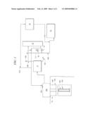
[0012]FIG. 1 is a schematic diagram of a lift gas capture and recycling apparatus representing one embodiment of the present invention;
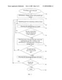
[0013]FIG. 2 is a flow chart showing an embodiment of a method of using the present invention.
DETAILED DESCRIPTION OF THE INVENTION
[0014]As used herein, the use of the word "a" or "an" when used in conjunction with the term "comprising" (or the synonymous "having") in the claims and/or the specification may mean "one," but it is also consistent with the meaning of "one or more," "at least one," and "one or more than one." In addition, as used herein, the phrase "connected to" means joined to or placed into communication with, either directly or through intermediate components.
[0015]Referring to FIG. 1, one embodiment of the present invention comprises wellbore 10, which includes annulus 100 between casing 101 and production tubing string 102. Subterranean fluids, also called wellbore fluids, are fluids that may be found in a wellbore, and may comprise, for example, natural gases, treatment gases, lift gases, air, treatment fluids, fracturing mixtures, water, hydrocarbons, drilling fluids, cuttings, salt, earthen materials, and the like. The composition of wellbore fluids usually changes throughout the lifecycle of a well. For instance, because many wells are treated with large amounts of fracturing fluids to fracture the well, wellbore fluids produced in the early stages of a well's life may be predominantly fracturing fluids.
[0016]When a well is producing mostly fracturing fluids, the fluid is referred to as flow back fluid. Newly fractured wells will initially produce flow back fluids until enough of the fluid is removed to allow larger quantities of other subterranean fluids, such as natural gas and/or oil, to be produced. It may take days or weeks to remove enough flow back fluid to allow a well to produce a desirable amount of gas or oil.
[0017]When a well is fractured, flow back fluid may at first be produced without the need for artificial lift, but in most cases, as the well pressure decreases it will eventually require artificial lift, such as gas lift. Gas lift involves directing a lift gas into a defined space such as a production tubing string to decrease the density of the fluid in the string, which results in the fluid being lifted to the surface. Lift gas may comprise any gas or combination of gasses, and often comprises nitrogen and/or natural gas.
[0018]Flow back fluids often comprise only small amounts of gas, sometimes called "early time gas." Prior art systems, believing the concentration of gas to be too small for other uses, either sent early time gas to flare or vented it to the atmosphere. In some cases, flow back fluids contain less that 50 standard cubic feet of gas per barrel of wellbore fluid produced ("SCF/bbl"), while in other cases it may contain less that 20, 10, or 5 SCF/bbl, or less.
Accumulation Phase
[0019]In one embodiment, the current invention captures the small amounts of early time gas in the flow back fluid, accumulates the gas, and uses the accumulated gas for gas lift. Wellbore fluids can be produced through well head 104 into separator 11. Separator 11 separates gas, which leaves separator 11 through gas line 106, from other materials, which leave separator 11 through line 107. Gas line 106 may include a vent 109 capable of venting to the atmosphere or to flare, but which is normally closed. While the system is accumulating gas, gas line 106 enters compressor 12, which directs the gas through valve 15 into lines 111 and 108. Gas volumes not returning to the compressor via line 111 will flow through line 108 to low pressure vessel 13.
[0020]As can be seen in FIG. 1, compressor 12 may direct gas to valve 15 or valve 14. However, when the system is accumulating lift gas, gas does not flow through valve 14 because a switch directs gas through valve 15 unless a condition is met to restrict flow through valve 15. In some embodiments, valve 14 is a check valve that operates at a higher pressure than valve 15, and thus when valve 15 is open, gas will flow through valve 15. In some embodiments, valve 14 is closed when valve 15 is open. In some embodiments, valve 15 is connected to a control mechanism 16 that can be triggered to close valve 15 upon the attainment of a condition, such as upon reaching a certain pressure. Control mechanism 16 may be connected to a variety of equipment, such as valve 15 or low pressure vessel 13.
[0021]As mentioned above, because gas line 106 carries so little gas (because the wellbore fluid contains so little gas), compressor 12 does not inject the gas into a pipeline or into wellbore 10 as lift gas. Instead, lines 108 and 111 allow compressor 12 to run in bypass mode to circulate a certain volume of gas from valve 15 through line 111 back to compressor 12 and to send any remaining gas to vessel 13. Because new gas continues to enter the system from separator 11 through line 106, the new gas flows from line 108 into low pressure vessel 13.
[0022]Low pressure vessel 13 accumulates gas until a first condition is reached, such as a certain high pressure reading relating to the pressure in the low pressure vessel 13. When the first condition is reached, valve 15 blocks flow, causing gas to flow from low pressure vessel 13, through compressor 12, through valve 14, and into wellbore 10. Compressor 12 directs gas from low pressure vessel 13 to wellbore 10 until a second condition is reached, such as a certain low pressure reading.
[0023]For example, the first condition may be a pressure of 70 psi, and the second condition may be a pressure of 30 psi. Of course, the first and second condition may be different pressures, either higher or lower than the examples given, provided the second condition is a lower pressure than the first condition. The pressure conditions may be determined by factors such as the well pressure, the constraints regarding back pressure on the well, the pressure rating of the equipment in the system, and safety factors, among others. In some embodiments, the first and second condition may be conditions other than pressure conditions, such as a timed interval.
[0024]Gas is injected through lift gas injection point 105 into wellbore 10. Lift gas injection point 105 may appear on well head 104 or it may enter into wellbore 10 or a portion thereof from another location. The amount of gas injected into wellbore 10 during any one accumulation phase will usually not be sufficient to direct gas through a gas lift valve in the wellbore. Thus, the accumulation cycle is repeated until wellbore 10 contains enough gas to send it through one or more gas lift valves, such as gas lift valve 103 attached to production tubing string 102.
[0025]In the embodiment shown in FIG. 1, the reason that the amount of gas injected into wellbore 10 during any one accumulation phase will usually not be sufficient to direct gas through a gas lift valve in the wellbore is that the gas must be of sufficient volume to displace wellbore fluid in annulus 100. In other words, before any gas is introduced into wellbore 10, wellbore fluid occupies annulus 100 and the inside of production tubing string 102. As gas from the accumulation cycle is directed by compressor 12 from low pressure vessel 13 into annulus 100, the level of the wellbore fluid in annulus 100 decreases in an amount corresponding to the amount of gas injected. By way of non-limiting example, wellbore 10 may be 1,000 feet deep, and gas lift valve 103 may be 800 feet deep. Thus, the system must inject sufficient gas in order to displace about 800 feet of wellbore fluid from annulus 100 in order to reach gas lift valve 103, which may require two or more accumulation and injection cycles. Of course, wellbore 10 may be deeper or shallower, and gas lift valve 103 may be located at different depths.
[0026]In some embodiments, lift gas may be injected into annulus 100, while in other embodiments it may be injected into a lift gas tubular (not shown) running alongside production tubing string 102. In a lift gas tubular embodiment, lift gas would accumulate in the lift gas tubular until it reaches a pressure sufficient to pass through the gas lift valve. In some embodiments, gas may be injected into a central tubular such as production tubing string 102 and the wellbore fluids produced through annulus 100. Those skilled in the art will recognize the many places into which lift gas may be injected in a wellbore. Hence, this specification and claims may refer generically to injecting gas into a wellbore, which includes, but is not limited to, injecting the gas as described in this paragraph.
[0027]In another embodiment, relatively small and inexpensive sources of lift gas are used to prime the system instead of, or in addition to, the accumulation of early time gas. For example, conventional nitrogen bottles can be drained directly into wellbore 10 and/or into low pressure vessel 13. Utilizing small, portable sources of charge gas avoids the need for expensive systems such as nitrogen trucks or nitrogen membrane generation systems.
Recycle Phase
[0028]Regardless which embodiment is used, once sufficient early time gas has been captured by the system, lift gas passes through gas lift valve 103 and into production tubing string 102. The injected gas lifts up through production tubing string 102 and into separator 11. At this stage, the system will recycle the injected lift gas. In the recycling phase, separated gas enters gas line 106 and travels to compressor 12. Because the volume of gas in the produced wellbore fluid is now greater than before the lift gas injection, compressor 12 may have adequate gas volumes to feed gas directly to reinjection. If gas volumes are not yet great enough to support full time recycling, the increased gas in the system will cause low pressure vessel 13 to fill up faster than before the lift gas injection, and thus the cycle for filling low pressure vessel 13 and injecting into wellbore 10 will occur more frequently during the recycling phase. This frequent cycling will not often last very long, perhaps only hours or less, at which point sufficient gas volumes have accumulated to support continued recycling.
[0029]During the recycling phase, low pressure vessel 13 acts as a buffer against fluid slugging and allows for a steady flow of gas to the compressor. This can be important in some situations, such as where the lift gas comes out of the well at an uneven rate.
[0030]Thus, during the recycling phase, the early time gas that was stored is reused, allowing a continuous or semi-continuous supply of lift gas and obviating or reducing the need for any additional outside lift gas. Further, during the recycling phase, early time gas and other gas may still be captured, thus increasing the total amount of lift gas available. Excess lift gas can be stored in a back up lift gas supply, such as high pressure vessel 17. High pressure vessel 17 can obtain excess gas from line 110 coming from compressor 12, or it can be filled with nitrogen or other gases.
Flow Diagrams
[0031]Referring to FIG. 2, in one embodiment a method provides a means for accumulating and recycling lift gas from a well, especially a well producing wellbore fluid with a small gas concentration. Oval 20 demonstrates providing a well that can benefit from gas lift. As mentioned, a variety of wells may benefit from the present invention, including oil and gas wells, gas wells, coal bed methane extraction wells, and the like. In some embodiments, as shown in box 21, a well system may optionally be charged with a portable gas source, such as nitrogen bottles. Charging the system expedites the process of obtaining enough gas to initiate gas lift in the system.
[0032]As shown in box 22, gas is separated from remaining wellbore fluids, and, per box 23, the separated gas is directed to a vessel. Diamond 24 demonstrates that the system directs separated gas to the vessel until the attainment of a condition. In some embodiments, the condition is a certain pressure. If the condition has not been attained, the system continues to separate gas and direct it to the vessel. If the condition has been attained, referring to box 25, the system directs some of the gas from the vessel into the wellbore. The amount of gas sent to the wellbore may be determined by a second condition, such as a second pressure achieved in the vessel. Optionally, some of the gas from the vessel may be diverted to a storage vessel.
[0033]Referring next to diamond 26, if the amount of gas injected into the wellbore is not sufficient to serve as lift gas (e.g., to pass through a gas lift valve), the cycle is repeated beginning at box 22. If enough gas has been injected, the injected gas is directed through one or more gas lift valves so that it can serve as lift gas, as shown in box 27. Referring to diamond 28, after injecting the lift gas, if desired, the process is repeated. By repeating the process, lift gas can be efficiently and effectively recycled with the vessel acting as a buffer vessel to create steady flows of lift gas. If the process is not repeated, for instance, where the well comes in and lift gas is not required, the process can end as shown in oval 29.
[0034]Some of the embodiments have been described for convenience with respect to flow back after fracturing a well, but the invention will work in a variety of embodiments for a variety of environments. The invention will work for any system that can benefit from lift gas, including systems that cannot or prefer not to utilize the lift gas from a traditional source. By way of non-limiting example, the invention will work with a well at any stage in its life cycle, wells producing little gas, wells with heavy oils, wells with low reservoir pressure, coal bed methane extraction wells, and the like.
[0035]As can be seen from the above description of certain embodiments of the present invention, the invention offers an inexpensive and efficient way to accumulate and/or recycle lift gas. Such a system can prevent costs and other difficulties from obtaining lift gas from an alternate source. Further, the invention allows operators to delay the decision of whether to tie a pipeline to a newly-drilled well, because the invention allows cheap lift gas production without a pipeline tie-in.
[0036]Although the present invention and its advantages have been described in detail, it should be understood that various changes, substitutions and alterations can be made herein without departing from the spirit and scope of the invention as defined by the appended claims. Moreover, the scope of the present application is not intended to be limited to the particular embodiments of the process, machine, manufacture, composition of matter, means, methods and steps described in the specification. As one of ordinary skill in the art will readily appreciate from the disclosure of the present invention, processes, machines, manufacture, compositions of matter, means, methods, or steps, presently existing or later to be developed that perform substantially the same function or achieve substantially the same result as the corresponding embodiments described herein may be utilized according to the present invention. Accordingly, the appended claims are intended to include within their scope such processes, machines, manufacture, compositions of matter, means, methods, or steps.
User Contributions:
comments("1"); ?> comment_form("1"); ?>Inventors list |
Agents list |
Assignees list |
List by place |
Classification tree browser |
Top 100 Inventors |
Top 100 Agents |
Top 100 Assignees |
Usenet FAQ Index |
Documents |
Other FAQs |
User Contributions:
Comment about this patent or add new information about this topic:
Images included with this patent application:
 |  |
 |
| Similar patent applications: | |
| Date | Title |
|---|---|
| 2013-01-24 | Remote manipulation and control of subterranean tools |
| 2012-12-20 | Managing treatment of subterranean zones |
| 2012-12-20 | Managing treatment of subterranean zones |
| 2010-03-04 | Bypass of damaged lines in subterranean wells |
| 2011-02-03 | Space-time surrogate models of subterranean regions |
| New patent applications in this class: | |
| Date | Title |
|---|---|
| 2016-09-01 | Method and system for optimizing well production |
| 2016-05-19 | Fissured substrata water pumping apparatus and method |
| 2016-05-12 | Downhole pumping apparatus and method |
| 2016-05-05 | Reciprocating electrical submersible well pump |
| 2016-04-21 | Plunger lift arrangement |
| Top Inventors for class "Wells" | |
| Rank | Inventor's name |
|---|---|
| 1 | Michael L. Fripp |
| 2 | Jean Marc Lopez |
| 3 | Michael H. Johnson |
| 4 | Jørgen Hallundbaek |
| 5 | Dennis P. Nguyen |