Patent application title: Railroad Track Model Servomotor Type Control System
Inventors:
Yu-Meng Yi (Pingjhen City, TW)
IPC8 Class: AG05D100FI
USPC Class:
701 19
Class name: Data processing: vehicles, navigation, and relative location vehicle control, guidance, operation, or indication railway vehicle
Publication date: 2009-01-01
Patent application number: 20090005922
Inventors list |
Agents list |
Assignees list |
List by place |
Classification tree browser |
Top 100 Inventors |
Top 100 Agents |
Top 100 Assignees |
Usenet FAQ Index |
Documents |
Other FAQs |
Patent application title: Railroad Track Model Servomotor Type Control System
Inventors:
Yu-Meng Yi
Agents:
HDSL
Assignees:
Origin: CHANTILLY, VA US
IPC8 Class: AG05D100FI
USPC Class:
701 19
Abstract:
A servomotor type control system for a railroad track model includes a
CPU, a key unit, and multiple servos; a player of the model achieves
control operating status of those servos as desired by operating the key
unit in conjunction with programming pre-installed in the CPU;
accordingly, multiple point rails can be easily controlled and adjusted;
the servo relates to a servomotor to allow rail switching highly
imitating life situation as a breakthrough of conventional restriction to
significantly upgrade delicate sense and precision of a railroad track
model.Claims:
1. A servomotor type control system for a railroad track model comprising
a central process unit (CPU), a key unit, and multiple servos; the CPU
containing pre-installed programs; the key unit connected to the CPU for
the CPU to send specific electronic signals according to setting of the
key unit; and the multiple servos being each related to a servomotor to
receive electronic signals transmitted from the CPU; and each servo to
change operation status of an output axle of the servo according to the
electronic signals transmitted from the CPU.
2. The servomotor type control system for a railroad track model as claimed in claim 1, wherein the key unit is comprised of three keys, respectively SELECT key, LEFT key, and RIGHT key.
3. The servomotor type control system for a railroad track model as claimed in claim 1, wherein the servos control point rail, switch signal, or crossing signal.
4. The servomotor type control system for a railroad track model as claimed in claim 1, wherein the output axle of the servo is capable of engaging in positive revolution output, inverse revolution output, and modulation of revolution speed.
5. The servomotor type control system for a railroad track model as claimed in claim 1, wherein the servo is fixed at where appropriately by a roadbed by means of an L brace; a servo horn is disposed to the output axle of the servo; the servo horn is linked to a steel rod; a terminal of the steel rod is engaged with a hook; the hook is disposed on a switch rod; and the switch rod is linked to and causes a point rail to move.
6. The servomotor type control system for a railroad track model as claimed in claim 1, wherein the servo is fixed at where appropriately beneath a roadbed by means of an L brace; a servo horn is disposed to an output axle of the servo; the servo horn is linked to a steel rod; a terminal at a top of the steel rod is upwardly linked to where between a sleeper and a switch rod; and the switch rod is linked to and causes a point rail to move.
7. The servomotor type control system for a railroad track model as claimed in claim 1, wherein a display device is disposed at where appropriately to the key unit.
8. The servomotor type control system for a railroad track model as claimed in claim 7, wherein the display device relates to an LED digital display.
Description:
BACKGROUND OF THE INVENTION
[0001](a) Field of the Invention
[0002]The present invention is related to an integrated system operated in a railroad track model for switching point rail, switch signal, or level crossing, and more particularly, to one achieving the control by a servomotor.
[0003](b) Description of the Prior Art
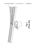
[0004]Train railroad track models generally available in the market involve making real traffic facilities into imitating miniature models including track, train on the track driven by electric energy, and point rail, crossing, related signals and environments to deliver sense of real situation for meeting imitation requirements. In a railroad track model of the prior as illustrated in FIG. 1 of the accompanying drawings, point rail controlling always operate by means of a stepping motor or an EM structure. The stepping motor or the EM structure usually is in a large size, which prevents easy installation and summary speed regulation, and involves complicate wiring. Even a player has to design on own efforts associate electronic devices; other players who do not command a certain level of electrics are unable to complete the installation of the railroad track model. Furthermore, existing control systems are found with poor coordination making operating set up extremely tedious and strenuous.
SUMMARY OF THE INVENTION
[0005]The present invention is to provide an integrated control system for a railroad track model to facilitate controlling and switching of multiple point rails or signals in the railroad track model. To achievement the purpose, the present invention of a railroad track servomotor type control system includes a CPU, a key unit, and multiple servos. The key unit permits a player to control and setup for deciding operation status of multiple servos as desired in conjunction with CPU programming.
[0006]The servo is made in a servomotor structure operating in conjunction with the CPU and the key unit to not only switch tracks but also adjust moving rate of the tracks, thus to allow easy performance of track switching at lower speed to better imitate real situation to satisfy players searching for a summary ways in approaching real requirements while the prior art permits only fast track switching based on a step motor.
[0007]The present invention by simply using a single key unit achieves integrated control to allow very easy and convenient setup and operation.
BRIEF DESCRIPTION OF THE DRAWINGS
[0008]FIG. 1 is a perspective view of the prior art.
[0009]FIG. 2 is a block chart showing a system configuration of the present invention.
[0010]FIG. 3 is a schematic view showing a disposition of a servo adapted in the present invention.
[0011]FIG. 4 is a schematic view showing another disposition of the servo adapted in the present invention.
DETAILED DESCRIPTION OF THE PREFERRED EMBODIMENTS
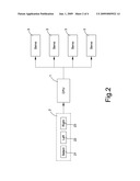
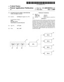
[0012]Referring to FIG. 2 for a block chart showing a configuration system of a preferred embodiment of the present invention, a railroad track servo type control system is essentially comprised of a central control unit (CPU) 1, key unit 2, and multiple servos 3.
[0013]The CPU 1 is a core of the system containing pre-installed programs.
[0014]The key unit 2 connected to the CPU 1 to command the CPU 1 to send specific electronic signals according to setting of the key unit 2. In the preferred embodiment, the key unit 2 includes three keys, respectively SELECT 21, LEFT 22, and RIGHT 23 though without limitation in practical application. The key unit 2 may be further provided with a display device, i.e., an LED digital display device to display setup status.
[0015]Four servos 3 are provided in the preferred embodiment though without limitation in practical application. The servo 3 controlling point rail, switch signal, crossing signal, etc., is related to a servomotor to receive electronic signals transmitted from the CPU 1 and capable of engaging in positive revolution for output, inverse revolution for output, and modulation of revolution speed.
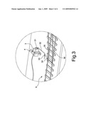
[0016]Now referring to FIG. 3 for a disposition of the servo 3 in the present invention, the servo 3 is fixed to where appropriate by a roadbed 9 by means of an L brace 4; a servo horn 31 is disposed to an output axle of the servo 3; the servo horn 31 is linked to a steel rod 32; a terminal of the steel rod 32 is coupled to a hook 33; the hook 33 is provided on a switch rod 34; and the switch rod 34 controls movement of two point rails 35, 36. Accordingly, when the servo 3 is activated, its output axle causes the servo horn 31 to swing for a certain angle thus to drive the steel rod 32 to travel to change positions of both point rails 35, 36 for achieving the purpose of adjusting both point rails 35, 36. As illustrated in FIG. 3, the servo 3 is disposed at where by the roadbed 9.
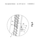
[0017]Alternatively, a servo 5 is disposed at where appropriately beneath the roadbed 9 as illustrated in FIG. 4 by means of the L brace 4; a servo horn 51 is provided to an output axle of the servo 5; the servo horn 51 is linked to a steel rod 52; a terminal at a top of the steel rod 52 is upwardly connected to where between a sleeper and the switch rod 54; and the switch rod 54 controls movement status of two point rails 55, 56.
User Contributions:
comments("1"); ?> comment_form("1"); ?>Inventors list |
Agents list |
Assignees list |
List by place |
Classification tree browser |
Top 100 Inventors |
Top 100 Agents |
Top 100 Assignees |
Usenet FAQ Index |
Documents |
Other FAQs |
User Contributions:
Comment about this patent or add new information about this topic:
Images included with this patent application:
 |  |
 |  |
 |
| Similar patent applications: | |
| Date | Title |
|---|---|
| 2012-03-15 | Method of controlling a hybrid powertrain to ensure battery power and torque reserve for an engine start and hybrid powertrain with control system |
| 2011-02-17 | Road grade coordinated engine control systems |
| 2011-11-24 | Hybrid working machine and servo control system |
| 2011-12-29 | Variable trim deflector system and method for controlling a marine vessel |
| 2009-12-31 | Automated throttle control system |
| New patent applications in this class: | |
| Date | Title |
|---|---|
| 2022-05-05 | Air supply system and method for controlling and/or monitoring an air supply system |
| 2019-05-16 | Automatic train protection method, vehicle on-board controller and train based on vehicle-vehicle communication |
| 2019-05-16 | Route resource controlling method, intelligent vehicle on-board controller and object controller |
| 2019-05-16 | Systems and method for a vehicle network |
| 2018-01-25 | Vehicle control system |
| Top Inventors for class "Data processing: vehicles, navigation, and relative location" | |
| Rank | Inventor's name |
|---|---|
| 1 | Anthony H. Heap |
| 2 | Ajith Kuttannair Kumar |
| 3 | Christopher P. Ricci |
| 4 | Roderick A. Hyde |
| 5 | Lowell L. Wood, Jr. |