Patent application title: Method and apparatus for balancing an HVAC system
Inventors:
John T. Kegley (Franklin, IN, US)
IPC8 Class: AF24F1308FI
USPC Class:
454284
Class name: Ventilation having inlet airway including specific air distributor (e.g., register, etc.)
Publication date: 2009-01-01
Patent application number: 20090004965
Inventors list |
Agents list |
Assignees list |
List by place |
Classification tree browser |
Top 100 Inventors |
Top 100 Agents |
Top 100 Assignees |
Usenet FAQ Index |
Documents |
Other FAQs |
Patent application title: Method and apparatus for balancing an HVAC system
Inventors:
John T. Kegley
Agents:
DANIEL J. O'CONNOR;PATENT ATTORNEY
Assignees:
Origin: INDIANAPOLIS, IN US
IPC8 Class: AF24F1308FI
USPC Class:
454284
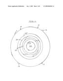
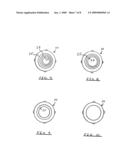
Abstract:
A method and apparatus for balancing an HVAC system. The method involves
using a plate which is circular in shape and has four inner cut-out
portions which are capable of being manually removed by an operating
engineer. To reduce flow to a minimum, all four rings are left on the
plate. To allow a progressively greater amount of air flow, more rings
are removed from the circular plate. Such enables the equalization of the
various rooms in an HVAC system without the addition of costly upstream
dampers. The circular plate is attached to a duct via four small
protruding ear elements.Claims:
1. A method of balancing and equalizing a heating, ventilating and air
conditioning system including the placement of a flow regulating and
metering plate in a duct leading to a room to be heated or cooled,wherein
the plate includes four inner removable ring elements,the plate further
including four outer attaching elements,wherein an innermost ring is
removed by an operating engineer to allow more air flow to a room to be
heated or cooled,wherein progressively more rings are removed to allow
more air to flow to a desired area.
2. The method of claim 1 wherein the plate is circular in shape and the outer attaching elements comprise small protruding ears which are sized to mate with the flexible portions of a standard heating or cooling duct.
3. A method of balancing and equalizing a heating, ventilating and air conditioning system which has at least three supply air ducts contained therein and at least three rooms to be heated or cooled comprising the steps of:placing an air flow control plate in at least one of said supply air ducts,placing a second air flow control plate in a second of said air supply ducts,adjusting said first and second air flow control plates by removing inner ring elements as needed to provide progressively more air flow to the rooms to be heated or cooled.
4. The method of claim 3 wherein each of said air flow control plates are circular and have multiple inner rings which are manually removable by an HVAC systems engineer.
5. The method of claim 4 wherein each of said air flow control plates have multiple small protruding ears at the edges thereof which are sized to be retained by a flexible portion of a supply duct.
6. An air flow regulating device for use in balancing and equalizing a heating, ventilating and air conditioning system comprising a plate having at least one inner element which is removable to allow increased air flow to a particular room or zone so that it may be restored to a certain desired temperature as compared to the rest of the HVAC system.
7. The air flow regulating device of claim 6 wherein said plate is in the shape of a circular disc and includes at least three removable inner rings, said rings being previously cut apart and spot welded back together so they can be easily removed by a systems engineer as desired.
8. The air flow regulating device of claim 7 and further including four outer duct attaching elements which comprise protruding ear-shaped units sized to pressure fit within the flexible portions of an HVAC duct.
Description:
BACKGROUND AND OBJECTS OF THE INVENTION
[0001]The present invention is generally related to the heating, ventilating and cooling (HVAC) arts in general and, in particular, to a novel metering orifice system and method of use.
[0002]Prior art HVAC ducting systems typically require the addition of a damper device with an associated access door in order to effectively control the air flow to a desired area.
[0003]Such damper air flow control devices are effective but costly and time consuming to install and use in practice.
[0004]HVAC maintenance and installing engineers are frequently called upon to balance a larger system by providing a certain desired air flow to a particular room or area.
[0005]Such must be done with precision and in a time-effective manner so the HVAC building customer is pleased with the outcome.
[0006]Accordingly, it is an object of the present invention to set forth a novel product comprising an adjustable metering orifice which allows the user to meter, adjust and/or proportion air flow in HVAC ducts.
[0007]It is also an object to describe a method of proportioning air flow in ducts in an economical manner, i.e. without having to install costly dampers and access means.
[0008]It is a further object of the invention to show a multi-orifice system which is initially fabricated as a unitary system which has breakaway components and retaining elements for ease of use by an installing and system adjusting engineer.
[0009]The system may be economically manufactured for widespread commercial appeal by those of skill in the HVAC arts.
[0010]These and other objects and advantages of the system and method of use will be apparent to those of skill in the art.
PRIOR ART PATENTS AND DESIGNS
[0011]During the course of preparing this specification for submission to the U.S. Patent and Trademark Office, a full search of the prior art was conducted.
[0012]U.S. Pat. No. 7,174,918 issued to Stevenson in 2007 teaches the use of an air flow control valve as part of an air conditioning module.
[0013]U.S. Pat. No. 5,228,475 issued to Trill in 1993 shows the use of an air flow control unit as used in a vehicle compartment.
[0014]U.S. Pat. No. 4,407,187 shows a ventilating air control device to regulate flow of air in a duct.
[0015]The invention is believed to be classified in Class 98 related to Ventilating Systems.
[0016]The particular structure and method of use for the structure are believed to be clearly patentable over all known designs in the heating, ventilating and air conditioning arts.
SUMMARY OF THE INVENTION
[0017]In order to eliminate hot spots or cold spots in a heating, ventilating and air conditioning (HVAC) system, a plate having four inner cut-out areas or removable portions is added to a duct just before it enters a room. To reduce air flow to a minimum, all of the cut-out portions or rings are left on the plate.
[0018]To allow more air flow to a room to be equalized, progressively more rings are removed from the plate by a systems operating engineer.
[0019]The plate includes four small outer protruding ear portions which are used, in conjunction with the more flexible portions of standard ducting, to mount the plate securely yet removably to the ducting.
[0020]The design saves system adjustment time and achieves a more balanced system in a very cost-effective manner.
[0021]The plates utilized may be easily removed and replaced as needed for future system adjustments.
BRIEF DESCRIPTION OF THE DRAWING FIGURES
[0022]FIG. 1 is a top view of a variable flow regulating plate as utilized in the inventive method.
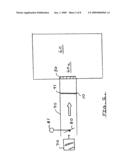
[0023]FIG. 2 is a basic example of how a metering plate is placed in an HVAC system to regulate air flow.
[0024]FIG. 3 illustrates a four room system to be balanced and related ducting and junction box units.
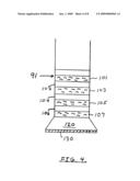
[0025]FIG. 4 shows the end portion of a ducting element in association with a diffuser box and discharge grille.
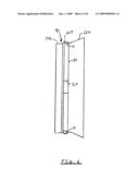
[0026]FIG. 5 is a view of the metering plate as placed in a duct and shows the method of removable attachment via the small protruding ears.
[0027]FIG. 6 is a side schematic view of the flow regulating plate as installed in the flexible portion of an HVAC duct.
[0028]FIGS. 7-10 show the flow regulator plate with various rings removed to allow progressively more air to flow to a room depending upon how a system needs to be balanced under particular high heat load or low heat load conditions.
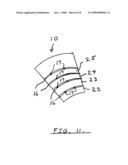
[0029]FIG. 11 shows structure of the air flow regulator.
FULL DESCRIPTION OF THE PREFERRED EMBODIMENTS
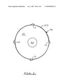
[0030]Referring to the drawing FIG. 1, the overall adjustable metering orifice unit is indicated at numeral 10 as having four duct attaching elements 11, 12, 13 and 14 to be further described.
[0031]The unit 10 has a central open area 20 to permit air flow.
[0032]The unit further has breakaway sections indicated at numerals 22, 23, 24 and 25. The breakaway sections are releasably attached to the unit and to each other by means of the connector elements indicated at the various numerals 17.
[0033]When the unit of FIG. 1 is placed in a HVAC duct, a certain measurable volume of air passes through the central opening 20.
[0034]Should a greater volume of air be needed to serve a certain area or room, as determined by an expert systems/installing engineer, the breakaway section 22 is removed to permit increased air flow.
[0035]As will be appreciated, the progressive sections 23, 24 and 25 may be broken away as needed to provide a certain desirable air flow.
[0036]FIG. 2 shows an overall system view and illustrates the method of the invention.
[0037]FIG. 2 shows a duct 40 having an area 41 which is near a discharge register, diffuser or grille 50 (to cite terms used in the art).
[0038]The register 50 directs air flow into a room 60 which has a region 60a at which the volume of air flow can be measured by an installing or system adjusting engineer.
[0039]FIG. 2 also shows the schematic HVAC system at 70 and a remote damper 80 operated via a type of controller 81 conventionally utilized in the HVAC and related arts.
[0040]In practice of the inventive method, the metering unit 10 is placed at area 41 of the duct 40 by simply removing the grille or register 50.
[0041]After the metering unit 10 has been placed in the duct at area 41 near the grille 50, the installing engineer can measure the air flow and system pressure at point 60a.
[0042]If such measurements are not as desired, the metering unit 10 can be easily changed by, for example, progressively removing sections 22, 23, 24 and 25 depending upon the particular conditions desired.
[0043]In such manner, the system flow can be accurately adjusted without the installing engineer having to go back to the remotely located damper 80.
[0044]Thus, significant amounts of time are saved and a more accurate system adjustment can be performed in a newly installed or existing heating, ventilating and air conditioning system.
[0045]It is contemplated that the adjustable metering unit 10 would be circular in shape to conform to most ducting, although other shapes, e.g. square or rectangular, may also be utilized.
[0046]FIG. 3 illustrates a larger system view which may, for example, comprise the office areas or zones on one floor of a building.
[0047]The HVAC unit 70 supplies cool or warm air via a larger duct 40 and damper 80 to a junction box shown at numeral 90. Junction box 90 is generally an enclosed, sealed compartment and comprises a distribution point for the supplied air.
[0048]The exit points from junction box 90 comprise ducts 91, 92, 93 and 94 and supply cool or warm air to rooms or zones 61, 62, 63 and 64 respectively.
[0049]As an example concerning original system design, it may have been assumed that office area 61 would accommodate four persons and four personal computers. Thus, to maintain a comfortable temperature of 72° F., a certain duct sizing and positioning would be designed. However, if office 61 ends up having only one person therein, the heat load is much lower than anticipated. Thus, the person occupying office 61 would most likely report the room to be too cold.
[0050]As is appreciated by systems engineers practicing in the HVAC arts, the remedy for such a "too cold" condition may be very costly and time consuming.
[0051]The flexible nature of duct 91 does not allow the installation of a conventional damper therein. To place a damper inside the closed and sealed junction box 90 would be time consuming, costly and difficult.
[0052]Similar problems may occur down the line in offices 62, 63 and 64 where a certain "typical average heat load" does not in fact exist.
[0053]This is the problem confronting the engineer assigned to balance or equalize a complex system with variable heat loads.
[0054]Especially in office building locations, the air outlet to the particular office is typically in the ceiling and not readily accessible to the occupant.
[0055]It has been discovered by the inventor herein that a specially designed metering and variable orifice unit can be utilized to remedy the situation.
[0056]Referring to FIG. 4, it is seen that a typical duct 91 used in the art is comprised of a series of alternating flexible portions such as reinforced cloth shown at numerals 101, 103, 105 and 107.
[0057]Duct 91 is further comprised of alternating harder sections 102, 104 and 106. Duct 91 is thus both durable and flexible.
[0058]The lower end of duct 91 is shown as attached to a typically rectangular diffuser element 120 having a removable grille 130 attached thereto.
[0059]Referring to FIG. 5, the air flow regulator 10 having central opening 20 is shown as installed in flexible section 107 of duct 91. As indicated, the small protruding ear elements 11-14 and thus the unit 10 are retained by the flexing action the material in duct section 107. Thus, unit 10 is secured in place and can also be easily removed as needed.
[0060]In the side schematic view of FIG. 6, the flow regulating plate 10 having central opening 20 is again shown as being retained in flexible area 107 of duct 91.
[0061]In the FIG. 6 view, the small protruding ears 11 and 13 are shown in relation to flexible duct area 107. Also indicated are the duct portion 106 and a part of the diffuser box 120.
[0062]Referring back to FIG. 3, it is noted that air flow regulating units can be installed in any or all of the ducts 91, 92, 93 and 94 as needed to balance a particular system.
[0063]Referring to FIGS. 7-10, the air flow metering and regulating plate 10 is shown with progressive ring sections removed to effect a variable air flow as needed.
[0064]In FIG. 7, ring 22 is removed.
[0065]In FIG. 8, ring 23 is removed.
[0066]In FIG. 9, ring 24 is removed.
[0067]In FIG. 10, ring 25 is removed to create the maximum air flow when the unit 10 is installed in a duct. The rings are manually removed by the HVAC engineer.
[0068]FIG. 11 shows detailed structure of the air flow metering and regulating unit 10. A partial section of unit 10 is shown.
[0069]A plurality of very small cuts 16, on the order of only 0.01 inch, are precision machine made to form the various rings 22-25. The rings are then spot-welded back together as indicated at numerals 17.
[0070]Such construction enables the rings 22-25 to be progressively removed at the option of the system engineer as a part of the balancing/equalizing process.
[0071]It is contemplated that the unit 10 would be made steel or equivalent durable materials and that various sizings would be made to accommodate particular duct sizes. The unit 10 could have an outer diameter on the order of 6 inches, 8 inches etc. for example.
[0072]In practice of the overall balancing method, it is noted that a single unit 10 could be placed in any of the supply ducts 91-94 and adjusted by the system engineer as needed.
[0073]While a particular structure and method of use have been shown and described, it is intended to cover equivalent structures and methods of use which would reasonably occur the those of skill in the art. For example, the unit 10 could be utilized in many types of HVAC systems other than described in FIG. 3. Also, the method of attaching unit 10 to a duct or other part of an HVAC system could be achieved by equivalent fastener means. The invention is further defined by the claims appended heteto.
User Contributions:
comments("1"); ?> comment_form("1"); ?>Inventors list |
Agents list |
Assignees list |
List by place |
Classification tree browser |
Top 100 Inventors |
Top 100 Agents |
Top 100 Assignees |
Usenet FAQ Index |
Documents |
Other FAQs |
User Contributions:
Comment about this patent or add new information about this topic:
Images included with this patent application:
 |  |
 |  |
 |  |
 |  |
 |
| Similar patent applications: | |
| Date | Title |
|---|---|
| 2013-02-07 | Telecom shelter cooling and control system |
| 2013-04-04 | Laminar air flow cage changing cabin made of plastic material |
| 2013-05-23 | Mixing device for an aircraft air conditioning system |
| 2011-11-10 | Vent sealing device and system |
| 2013-04-18 | Powered diaphragm air extractor and control system |
| New patent applications in this class: | |
| Date | Title |
|---|---|
| 2016-06-30 | Air discharge device and air conditioner having the same |
| 2015-10-22 | Air-conditioning unit |
| 2015-05-28 | Universal inlet duct system for side air intake equipment |
| 2015-05-21 | Decorative air conduit |
| 2015-05-21 | Air conditioning units |
| Top Inventors for class "Ventilation" | |
| Rank | Inventor's name |
|---|---|
| 1 | Dariusz Krakowski |
| 2 | Alan L. Browne |
| 3 | Paul Bryan Hoke |
| 4 | Darrell Horner |
| 5 | Chao-Ke Wei |