Patent application title: Adjustment Method, Particularly a Laser Adjustment Method, and an Actuator Suitable for the Same
Inventors:
Burkhard Muller (Munich, DE)
Robert Burns Israelsen (North Salt Lake, UT, US)
IPC8 Class: AB29D1100FI
USPC Class:
264 127
Class name: Optical article shaping or treating optical fiber, waveguide, or preform utilizing plasma, electric, electromagnetic, particle, or wave energy
Publication date: 2008-12-25
Patent application number: 20080315443
Inventors list |
Agents list |
Assignees list |
List by place |
Classification tree browser |
Top 100 Inventors |
Top 100 Agents |
Top 100 Assignees |
Usenet FAQ Index |
Documents |
Other FAQs |
Patent application title: Adjustment Method, Particularly a Laser Adjustment Method, and an Actuator Suitable for the Same
Inventors:
Burkhard Muller
Robert Burns Israelsen
Agents:
Workman Nydegger;1000 Eagle Gate Tower
Assignees:
Origin: SALT LAKE CITY, UT US
IPC8 Class: AB29D1100FI
USPC Class:
264 127
Abstract:
The invention relates to an adjustment method, especially for the
adjustment of optical or fibre optical components, whereby a partial
region of an actuator is locally heated in such a defined manner that
compressive stresses are created therein as a result of the restricted
thermal expansion of said heated partial region, caused by at least one
other partial region of the actuator. If the yielding point σ of
the material of the partial region is exceeded, said compressive stresses
lead to the plastic compression of the heated partial region.
Furthermore, said heated partial region is contracted during cooling and
leads to a defined modification of the geometry of the actuator following
the cooling process. Tensile stresses are created as a result of a
restriction of said contraction by means of at least one other partial
region in the previously heated partial region, and compressive stresses
are frozen in the at least one other region. During the adjustment
process, essential regions of the actuator, in which the tensile stresses
or compressive stresses are frozen after cooling, are brought to a
critical temperature in relation to the operating temperature of the
actuator, at least until flow processes of the material are ended at the
critical temperature.Claims:
1-7. (canceled)
8. A method for adjusting optical or fiber optic components, comprising:locally heating a selected subregion of an actuator such that compressive stresses arise in the selected subregion, which, upon reaching a yield point of the material of the selected subregion, results in plastic deformation of the selected subregion; andcooling the selected subregion, such that the selected subregion is shortened, resulting in a defined geometric change of the actuator, wherein tensile stresses arise in a first subregion of the actuator and, in a second region of the actuator, the compressive stresses are frozen, wherein:a region of the actuator in which the tensile stresses or compressive stresses exist after cooling is brought to a critical temperature with regard to a usage temperature range of the actuator, at least until flow processes of the material at the critical temperature are substantially concluded.
9. The method of claim 8, wherein the compressive stresses arise from thermal expansion of the selected subregion being substantially constrained by an adjacent subregion of the actuator.
10. The method of claim 8, wherein the critical temperature is selected to be essentially the temperature within the usage temperature range at which the minimum yield point of the material is attained.
11. The method of claim 8, wherein the material of the selected subregion of the actuator has a yield point that drops monotonically, at least within the usage temperature range.
12. The method of claim 11, wherein the critical temperature is selected to be essentially the temperature at an upper limit of the usage temperature range.
13. The method of claim 8, further comprising brining an entire subassembly that includes the actuator to the critical temperature.
14. The method of claim 8, wherein locally heating the selected subregion is performed using an Nd:YAG laser.
15. The method of claim 8, wherein locally heating the selected subregion is performed using a diode laser.
16. An actuator for adjusting an optical or a fiber optics component, comprising:means for locally heating a selected subregion of the actuator such that compressive stresses arise in the selected subregion, which, upon reaching a yield point of the material of the selected subregion, results in plastic deformation of the selected subregion; andmeans for cooling the selected subregion, such that the selected subregion is shortened, resulting in a defined geometric change of the actuator, wherein tensile stresses arise in a first subregion of the actuator and, in a second region of the actuator, the compressive stresses are frozen, wherein:a region of the actuator in which the tensile stresses or compressive stresses exist after cooling is brought to a critical temperature with regard to a usage temperature range of the actuator, at least until flow processes of the material at the critical temperature are substantially concluded.
17. The actuator of claim 16, wherein at least the selected subregion of the actuator is formed from a material having a yield point that assumes a minimum value within the entire usage temperature range essentially at room temperature.
18. The actuator of claim 16, wherein the means for locally heating the selected subregion comprises a laser.
19. The actuator of claim 18, wherein the laser comprises an Nd:YAG laser.
20. The actuator of claim 18, wherein the laser comprises a diode laser.
21. The actuator of claim 16, further comprising:a base;an adjustment region that moves in response to the means for locally heating and the means for cooling; anda pair of double bridges that connect the base and the adjustment region, wherein the selected subregion is included in on of the bridges of the pair of double bridges.
22. The actuator of claim 16, wherein the critical temperature is selected to be essentially the temperature within the usage temperature range at which the minimum yield point of the material is attained.
23. The actuator of claim 16, wherein the material of the selected subregion has a yield point that drops monotonically within the usage temperature range.
24. The actuator of claim 23, wherein the critical temperature is selected to be essentially the temperature at an upper limit of the usage temperature range.
Description:
[0001]The invention concerns an adjustment method, particularly for
adjusting optical or fiber optical components, with the features of the
preamble of patent claim 1. Moreover, the invention concerns an actuator
which is suitable for the same.
[0002]Laser adjustment methods and actuators suitable for the same have been developed in recent times to enable extremely precise adjustment, e.g., of micromechanical components.
[0003]The basic principle of laser adjustment consists of heating a predetermined region of an actuator using a high-energy, preferably pulsed laser beam in a short time, in which the thermal expansion of the relevant region is blocked by corresponding further regions of the actuator. In this manner, compression strains build up in this heated region, which result in a plastic deformation of this region upon reaching the yield point. When this region is cooled down after the high-energy laser beam is switched off, the thermal shrinkage of this region is again essentially prevented by the further regions of the actuator. This leads to the build-up of tensile stresses in the previously heated region which lead to a defined deformation of the actuator, in which the adjustment of a component joined to the actuator is enabled in this process.
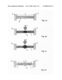
[0004]The basic principle of such an adjustment method is illustrated in FIG. 1. FIG. 1a shows the starting state of a bar 3 made of a suitable material which is restrained between two rigid demarcations 1. At the starting temperature, e.g., room temperature (20° C.), the bar 3 has a length l0. The center region 3a of the bar 3 is heated by a laser beam 5 in a short time.
[0005]This results in the first place in compressive stresses σ.sup.(-) in the bar 3 since the thermal longitudinal expansion of the bar 3 is blocked by the rigid demarcations 1. In this phase, a negative expansion ε is also customarily defined which corresponds to the compressive stresses formed in the bar 3. This phase of the adjustment method is illustrated in FIG. 1b.
[0006]If the compressive stresses σ.sup.(-) exceed the temperature-dependent yield point σF, a plastic deformation of the bar 3 arises in the region 3a. Correspondingly, the compressive stresses in the bar 3 are reduced. This situation is illustrated in FIG. 1c.
[0007]After the laser beam 5 is switched off, the region 3a of the bar 3 begins to cool off, causing a thermal shrinkage of the bar 3. In this process, tensile stresses σ.sup.(+) arise in the bar 3 which in actual practice frequently lie in the vicinity of the temperature-dependent yield point σF(T). This situation is represented symbolically in FIG. 1d because seen in the longitudinal direction of the bar 3 whose ends are joined by means of spring elements 7 to the rigid demarcations 1 . . . [Note: incomplete sentence in the German original]. The spring forces corresponding to the tensile stresses σ.sup.(+) cause a defined deformation of the actuator in a practically realized actuator. In this connection, FIG. 1d also shows that the tensile stresses σ.sup.(+) arise through the shortening of the bar 3 due to the plastic deformation in the region 3a caused during the heating, in which the length of the bar l1 after the adjustment procedure at the starting temperature is smaller than the original length l0 at the starting temperature.
[0008]A problem in the previously known adjustment methods consists in that, as was previously mentioned, the tensile stresses frozen in the bar 3 lie relatively close to the yield point σF. The same can apply also to the compressive stresses which occur in those regions which block the thermal expansion or rather the thermal shrinkage of the bar. Since micromechanical or optical components or rather subassemblies in actual practice are always specified for a certain temperature range, e.g., a range from -40° C. to +80° C., and must fulfill predetermined requirements for accuracy and long-term stability within the specified range, there results in previously known adjustment methods a maladjustment of the actuator if the adjusted components or rather the subassembly is brought to a temperature in the upper region of the specified range and the original adjustment was carried out at a significantly lower temperature, such as room temperature. This effect is caused by the temperature dependency of the yield point σF, most materials which are suitable for the manufacture of actuators for laser adjustment methods having a yield point which decreases with increasing temperature. If a temperature is reached at which the yield point σF falls below the value of the frozen-in tensile stresses, this results in a flowing of the material and in a reduction of the tensile stresses to the value of the yield point σF at the relevant temperature. Naturally, this is associated with a corresponding maladjustment of the actuator which is not acceptable at least for components requiring extremely precise adjustment which must be specified over a wide temperature range.
[0009]The underlying object of the invention is therefore to create an adjustment method, particularly for adjusting optical or fiber optical components, with which improved long-term stability of an adjusted actuator or rather a subassembly having such an actuator can be ensured within a predetermined temperature range, it being possible to carry out the method quickly and at a low cost. Moreover, the underlying object of the invention is to create a special actuator for simply carrying out the method.
[0010]This objective is solved by the invention with the features of patent claim 1 or 6.
[0011]The invention is based on the insight that the adjustment of an actuator can be carried out in an advantageous manner at a critical temperature Tk with regard to the predetermined usage temperature range of the actuator. In this connection, a critical temperature Tk is understood to be a temperature at which the yield point has a value such that when passing through the entire usage temperature range, only minor maladjustments of the adjusted actuator can occur which lie within specified tolerances. With conventional actuator materials, which have within a specification range a yield point that decreases at higher temperatures, one will choose the critical temperature in the upper region of the specification range or even a temperature lying above its upper limit To.
[0012]According to an embodiment of the invention, the critical temperature Tk can essentially be chosen to be that temperature within the usage temperature range at which the minimum yield point σF of the material is attained within the usage temperature range. In this case, it is ensured that within the usage temperature range, no flowing of the material occurs in those regions of the actuator in which internal stresses occur as a result of the adjustment procedure.
[0013]The possibility explained above of selecting an even higher temperature is limited in actual practice by the fact that often such components are also contained in subassemblies which may be subjected as a maximum temperature to the upper temperature To of the usage temperature range.
[0014]According to an embodiment of the method, an entire subassembly including the actuator can be brought to the critical temperature Tk during the adjustment procedure. If only subregions of the actuator are brought to the critical temperature Tk during the adjustment procedure, at least those regions must be included which are subject to thermal shrinkage but also those which prevent such shrinkage.
[0015]A special actuator with which the method according to the invention can be implemented in a particularly simple manner is formed such that at least the essential regions of the actuator consist of a material whose yield point σF assumes a minimum value within the entire usage temperature range essentially at room temperature. Using an actuator of this sort, an adjustment procedure can be carried out as usual at room temperature.
[0016]According to an embodiment of the invention, the actuator or rather the essential regions of the actuator can consist of a material whose yield point does not drop or rather remains essentially constant over the entire usage temperature range. For example, TiV13Cr11A13 can be used as a material for the actuator or rather the essential regions of the actuator. The 0.2% permanent elongation limit, resistance to extension and yield point of this material does not decrease measurably up to a temperature of 100° C.
[0017]Further embodiments of the invention follow from the dependent claims.
[0018]The invention is described hereafter in greater detail based on the figures shown in the drawing. The figures are as follows:
[0019]FIG. 1: Schematic representations of the laser beam adjustment method;
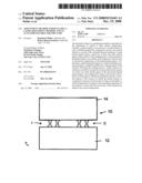
[0020]FIG. 2: An embodiment of a practical actuator having two double bridges; and
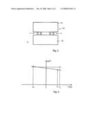
[0021]FIG. 3: A chart showing the temperature-dependent yield point σF(T) in a conventional actuator material within a usage temperature range [Tu;To].
[0022]The laser beam adjustment method explained in basic terms in the introduction is illustrated again briefly in greater detail based on a practical actuator 10 shown in FIG. 2. The actuator 10 consists of a base region 12 which is joined by means of two double bridges I, II to an adjustment region 14. For adjustment purposes, in each case one of the two bridges of the double bridges I, II is irradiated preferably in the center (in relation to the longitudinal axis of a bridge) using a high-power laser beam. For example, if the bridge shown to the left in FIG. 2 of the double bridge I is heated in its center region using the laser beam, then the affected bridge attempts to expand, the thermal expansion being essentially blocked by the right bridge of the double bridge I. In this process, the left double bridge is deformed in its center region. During the cooling, the left bridge of the double bridge I attempts to draw together, through which corresponding tensile stresses arise in it in this process, since this movement is also blocked largely by the right bridge. If in a next step the center region of the bridge shown to the right in FIG. 2 of the double bridge I is also irradiated using the laser, then this region will be deformed due to the tensile stresses present in the left bridge and the compressive stress present in the right bridge (in addition to the compressive stresses which are caused by a thermal expansion of the right bridge). During the cooling, the right bridge of the double bridge I attempts to draw together further, such that this movement is blocked in turn by the left bridge. Accordingly, internal stresses remain, which are formed in the right bridge as tensile stresses and in the left bridge as compressive stresses.
[0023]As a result of this adjustment procedure, the adjustment region 14 is tilted slightly with respect to the starting position shown in FIG. 2 using a continuous line as a result of the shortening of the two bridges of the double bridge I. This situation is illustrated in FIG. 2 using a dashed line. In this manner, an adjustment of the angle of a component (not shown) arranged on the adjustment region 14 can occur. If the right double bridge II is also adjusted correspondingly, then highly precise adjustment of a component arranged on the adjustment region 14 can occur in the longitudinal direction of the bridges.
[0024]If the adjustment procedures are carried out at an critical temperature Tk, in which it is necessary for at least the double bridge to be adjusted or rather for both double bridges to be adjusted to be at this temperature, then upon suitable choice of the critical temperature Tk only such internal stresses are frozen in as a consequence of the adjustment procedure(s) which, even in case of longer-term storage of the actuator 10 at an arbitrary temperature within a predetermined usage temperature range [Tu;To], lead to such maladjustments that lie within acceptable tolerances.
[0025]If, for example, the actuator material exhibits the curve of its temperature-dependent yield point σF(T) shown in FIG. 3 as a continuous line, then one will choose, as shown in FIG. 3, the critical temperature Tk in the upper region of the usage temperature range [Tu;To]. The critical temperature Tk must be chosen for the monotonically decreasing curve of the yield point σF(T) shown in FIG. 3 to be so high that even in case of longer-term storage of the actuator at the upper limit Tu of the usage temperature range only such a maladjustment will occur as a consequence of a reduction in internal stresses in the essential regions of the actuator that lies within specified permissible tolerances.
[0026]If one assumes that in the essential regions of the actuator internal stresses are frozen in which lie extremely close to the yield point at the critical temperature or rather the adjustment temperature chosen in each case, then a maladjustment in case of longer-term storage of the actuator at the temperature To can be avoided in full only if the critical temperature Tk is chosen to be equal to the upper range limit To.
[0027]If a material is chosen for the actuator or its essential regions whose yield point σF(T) over the entire usage temperature range [Tu;To] is essentially constant, then the critical temperature Tk can be chosen arbitrarily. Here, one will preferably choose the temperature Tk in the room temperature range to achieve the lowest cost.
[0028]Finally, it should be mentioned that the heating of the essential regions of the actuator, the overall actuator or an overall subassembly including the actuator can take place, for example, through irradiation with an infrared radiation source by using a customary, heated temperature chamber or a heated holder, or even using a laser beam which, suitably expanded, is either aimed at the essential regions or which "scans" the essential regions at a suitable speed.
User Contributions:
comments("1"); ?> comment_form("1"); ?>Inventors list |
Agents list |
Assignees list |
List by place |
Classification tree browser |
Top 100 Inventors |
Top 100 Agents |
Top 100 Assignees |
Usenet FAQ Index |
Documents |
Other FAQs |
User Contributions:
Comment about this patent or add new information about this topic:
Images included with this patent application:
 |  |
 |
| New patent applications in this class: | |
| Date | Title |
|---|---|
| 2016-06-30 | Plasma deposition process with removal of substrate tube |
| 2016-06-09 | Systems and methods for multiple-pass stripping of an optical fiber coating |
| 2016-06-02 | Plasma deposition process with removal of substrate tube |
| 2016-05-19 | Methods of producing three-dimensional objects from materials having multiple mechanisms of hardening |
| 2016-05-12 | Methods for stripping an optical fiber coating using blue or blue-violet radiation |
| Top Inventors for class "Plastic and nonmetallic article shaping or treating: processes" | |
| Rank | Inventor's name |
|---|---|
| 1 | Shou-Shan Fan |
| 2 | Byung-Jin Choi |
| 3 | Yunbing Wang |
| 4 | Gene Michael Altonen |
| 5 | Sander Frederik Wuister |