Patent application title: Method for fabricating heat-dissipating base structure
Inventors:
Pai-Yi Huang (Taipei, TW)
Assignees:
Inventec Corporation
IPC8 Class: AB21D5308FI
USPC Class:
2989003
Class name: Metal working method of mechanical manufacture heat exchanger or boiler making
Publication date: 2008-12-25
Patent application number: 20080313902
Inventors list |
Agents list |
Assignees list |
List by place |
Classification tree browser |
Top 100 Inventors |
Top 100 Agents |
Top 100 Assignees |
Usenet FAQ Index |
Documents |
Other FAQs |
Patent application title: Method for fabricating heat-dissipating base structure
Inventors:
Pai-Yi Huang
Agents:
EDWARDS ANGELL PALMER & DODGE LLP
Assignees:
Inventec Corporation
Origin: BOSTON, MA US
IPC8 Class: AB21D5308FI
USPC Class:
2989003
Abstract:
A method for fabricating a heat-dissipating base structure is disclosed.
The method includes (1) providing a plurality of heat-dissipating fins
arranged in parallel, each having at least a first through hole and a
second through hole corresponding to the first through hole formed
thereon at corresponding positions; (2) providing at least a U-shaped
heat-dissipating tube having two tube foot portions and a bending
portion, wherein the diameter of the two tube foot portions is smaller
than that of the first and second through holes and the two tube foot
portions are inserted into the first and second through holes
respectively; (3) performing a dispensing process by penetrating a
dispensing tip into the spacing between the U-shaped heat-dissipating
tube and the first and second through holes of the heat-dissipating fins;
(4) providing a base having a surface for dispensing and mounting the
parallel-aligned heat-dissipating fins on the dispensed surface of the
base; (5) using at least a clamp tool to tighten the base, the
heat-dissipating fins and the U-shaped heat-dissipating tube to be placed
in an oven for heating and the subsequent soldering process; and (6)
removing the heat-dissipating base from the oven after the heating
process and removing the clamp tool after the heat-dissipating base cools
off and is fixedly assembled.Claims:
1. A method for fabricating a heat-dissipating base structure, comprising
the steps of:(1) providing a plurality of heat-dissipating fins arranged
in parallel, each having at least a first through hole and a second
through hole corresponding to the first through hole formed thereon at
corresponding positions;(2) providing at least a U-shaped
heat-dissipating tube having two tube foot portions and a bending
portion, wherein the diameter of the two tube foot portions is smaller
than that of the first and second through holes and the two tube foot
portions are inserted into the first and second through holes
respectively;(3) performing a dispensing process by penetrating a
dispensing tip into the spacing between the U-shaped heat-dissipating
tube and the first and second through holes of the heat-dissipating
fins;(4) providing a base having a surface for dispensing and mounting
the parallel-aligned heat-dissipating fins on the dispensed surface of
the base;(5) performing a heating process by using at least a clamp tool
to tighten the base, the heat-dissipating fins and the U-shaped
heat-dissipating tube to be placed in an oven for heating and a
subsequent soldering process; and(6) removing the heat-dissipating base
from the oven after the heating process and removing the clamp tool after
the heat-dissipating base is cooled off and is fixedly assembled.
2. The method of claim 1, wherein the first through hole is elliptic.
3. The method of claim 1, wherein the second through hole is elliptic.
4. The method of claim 1, wherein the first through hole and the corresponding second through hole are arranged in a vertical line.
5. The method of claim 1, wherein the first through hole and the corresponding second through hole are arranged in a horizontal line.
6. The method of claim 1, wherein the U-shaped heat-dissipating tube is fixed to one side of the first and second through holes by a conductive material through a soldering method.
7. The method of claim 6, wherein the conductive material is one of gold, silver, solder paste, and a mixture thereof.
8. The method of claim 1, wherein the clamp tool of the step (5) comprises a heat-dissipating tube clamp tool.
9. The method of claim 8, wherein the heat-dissipating tube clamp tool is a metal bar, which is inserted into the spacing between the U-shaped heat-dissipating tube and the first and second through holes of the heat-dissipating fins so as to make the tube foot portions of the U-shaped heat-dissipating tube closely attached to one side of the first and second through holes of the heat-dissipating fins.
Description:
BACKGROUND OF THE INVENTION
[0001]1. Field of the Invention
[0002]The present invention relates generally to a method for fabricating a heat-dissipating base structure, and more particularly to a method for fabricating a heat-dissipating base structure having a U-shaped heat-dissipating tube.
[0003]2. Description of Related Art
[0004]In a conventional heat-dissipating base having a heat-dissipating tube, in order to solder the heat-dissipating tube to heat-dissipating fins, a dispensing process comprising the following steps has to be performed: first, a groove or a hole is formed on upper side of heat-dissipating tube holes of the heat-dissipating fins, wherein the heat-dissipating tube is inserted into the heat-dissipating fins through the heat-dissipating tube holes; then, a dispensing tip is inserted into the groove or the hole so as to dispense solder paste between the heat-dissipating tube and the heat-dissipating fins, the solder paste at a melting state further flows through the spacing between the heat-dissipating tube and the heat-dissipating fins by gravitational force and capillary force, thereby filling space between the heat-dissipating tube and the heat-dissipating fins. However, the natural drain down of the solder paste cannot ensure the heat-dissipating tube and the heat-dissipating fins are completely soldered together. If the heat-dissipating tube and the heat-dissipating fins are not completely soldered together, the heat transfer effect from the heat-dissipating tube to the heat-dissipating fins will be adversely affected, which further adversely affects the heat-dissipating efficiency of the heat-dissipating base.
[0005]Referring to FIGS. 1A and 1B, a conventional heat-dissipating base having a heat-dissipating tube comprises a base 10; a plurality of heat-dissipating fins 11 arranged in parallel and disposed on the base 10, wherein each of the fins 11 has a plurality of heat-dissipating tube holes 110; and a U-shaped heat-dissipating tube 20, two tube foot portions of which are inserted into the heat-dissipating tube holes 110 of the heat-dissipating fins 11. On upper side of the heat-dissipating tube holes 110 there are disposed openings 111 as shown in FIG. 1A or grooves 112 as shown in FIG. 1B such that a dispensing tip (not shown) can be inserted into inside of the heat-dissipating fins 11 through the openings 111 or the grooves 112 for dispensing such that solder paste can be attached to the U-shaped heat-dissipating tube 20.
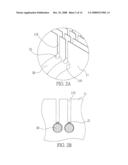
[0006]As shown in FIG. 2A, after a dispensing process is performed to the structure of FIG. 1B, the whole heat-dissipating base structure is put into an oven such that the solder paste 21 can be melted. The melted solder paste 21 further flows through and fills spacing between the heat-dissipating tube 20 and the heat-dissipating tube holes 110 of the heat-dissipating fins 11 by gravitational force and capillary force, thereby soldering together the U-shaped heat-dissipating tube 20 and the heat-dissipating fins 11.
[0007]However, the natural drain down of the solder paste 21 cannot ensure the heat-dissipating tube and the heat-dissipating fins are completely soldered together. As shown in FIG. 2B, spacing between the lower portion of the U-shaped heat-dissipating tube 20 and the heat-dissipating tube holes 110 of the heat-dissipating fins 11 is not filled with the solder paste 21, which can adversely affect the heat transfer effect from the heat-dissipating tube 20 to the heat-dissipating fins 11 and the heat-dissipating effect of the heat-dissipating base.
[0008]Further, since the diameter of the heat-dissipating tube holes 110 corresponds to the diameter of the U-shaped heat-dissipating tube 20, once the U-shaped heat-dissipating tube 20 is inserted into the heat-dissipating tube holes 110, the U-shaped heat-dissipating tube 20 cannot make any displacement. Therefore, it is not possible to perform a dispensing process to the lower tube foot portion of the U-shaped heat-dissipating tube 20. Correspondingly, an opening or a groove similar to the above-mentioned opening or groove also needs to be formed for allowing a dispensing tip to enter into inside of the heat-dissipating fins such that the lower tube foot portion can be soldered to the heat-dissipating fins. However, in the prior art, no such opening or groove is formed taking into account of such factors as heat-dissipating area. Instead, the lower tube foot portion of the U-shaped heat-dissipating tube 20 is kept separated from the heat-dissipating fins 11, which thus leads to a poor heat conduction therebetween and accordingly reduces the heat-dissipating effect of the heat-dissipating base.
[0009]Therefore, how to overcome the above drawback has become urgent.
SUMMARY OF THE INVENTION
[0010]According to the above drawbacks, an objective of the present invention is to provide a method for fabricating a heat-dissipating base structure having heat-dissipating fins having elliptic through holes.
[0011]Another objective of the present invention is to provide a method for fabricating a heat-dissipating base structure, through which the heat-dissipating tube can obtain a good soldering effect.
[0012]A further objective of the present invention is to provide a method for fabricating a heat-dissipating structure having good heat-dissipating efficiency.
[0013]In order to attain the above and other objectives, the present invention discloses a method for fabricating a heat-dissipating structure, wherein a heat-dissipating tube can be moved in the elliptic through hole and secured fast to one side of the through hole.
[0014]The method for fabricating the heat-dissipating base structure comprises the steps of: [0015](1) providing a plurality of heat-dissipating fins arranged in parallel, each having at least a first through hole and a second through hole corresponding to the first through hole formed thereon at corresponding positions; [0016](2) providing at least a U-shaped heat-dissipating tube having two tube foot portions and a bending portion, wherein the diameters of the two tube foot portions are smaller than the diameters of the first and second through holes and the two tube foot portions are inserted into the first and second through holes respectively; [0017](3) performing a dispensing process by penetrating a dispensing tip into the spacing between the U-shaped heat-dissipating tube and the first and second through holes of the heat-dissipating fins; [0018](4) providing a base having a surface for dispensing and mounting the parallel-aligned heat-dissipating fins on the dispensed surface of the base; [0019](5) using at least a clamp tool to tighten the base, the heat-dissipating fins and the U-shaped heat-dissipating tube to be placed in an oven for heating and the subsequent soldering process; and [0020](6) removing the heat-dissipating base from the oven after the heating process and removing the clamp tool after the heat-dissipating base cools off and is fixedly assembled.
[0021]Preferably, the first and second through holes are elliptic. The first and second through holes can be arranged in a vertical line or in a horizontal line. The U-shaped heat-dissipating tube is fixed to one side of the first and second through holes by a conductive material through a soldering method. The conductive material is one of gold, silver, solder paste, and a mixture thereof. The clamp tool of step (5) comprises a base clamp and a heat-dissipating tube clamp, wherein the heat-dissipating tube clamp is a metal bar to be inserted into the spacing between the U-shaped heat-dissipating tube and the first and second through holes of the heat-dissipating fins so as to make the tube foot portions of the U-shaped heat-dissipating tube closely attached to one side of the first and second through holes of the heat-dissipating fins.
[0022]Compared with the prior art that solders the heat-dissipating tube and the heat-dissipating fins together by forming little through holes for inserting of a dispensing tip so as to dispense the solder material and make the soldering material fill the spacing between the heat-dissipating tube and the heat-dissipating fins through the gravitational force of the solder material and capillary force formed in the spacing between the heat-dissipating tube and the heat-dissipating fins, the present invention can make the heat-dissipating tube closely attached and soldered to one side of the through holes by an external force so as to obtain a good heat conducting effect between the heat-dissipating tube and the heat-dissipating fins, thereby improving the heat-dissipating efficiency of the whole heat-dissipating base structure.
BRIEF DESCRIPTION OF DRAWINGS
[0023]FIG. 1A is a diagram of a conventional heat-dissipating base structure having holes formed for insertion of a dispensing tip;
[0024]FIG. 1B is a diagram of a conventional heat-dissipating base structure having grooves formed for insertion of a dispensing tip;
[0025]FIG. 2A is a partially expanded diagram showing a state after solder paste is dispensed to the structure of FIG. 1B;
[0026]FIG. 2B is a partially expanded diagram showing a soldering state between the heat-dissipating tube and the heat-dissipating fins of the heat-dissipating base structure of FIG. 2A;
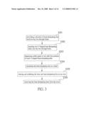
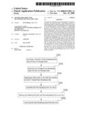
[0027]FIG. 3 is a diagram showing a method for fabricating a heat-dissipating base structure according to a first embodiment of the present invention;
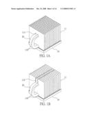
[0028]FIG. 4A is a diagram showing step (1) of the method for fabricating a heat-dissipating base structure according to a first embodiment of the present invention;
[0029]FIG. 4B is a diagram showing step (2) of the method for fabricating a heat-dissipating base structure according to a first embodiment of the present invention;
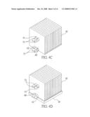
[0030]FIG. 4C is a diagram showing step (3) of the method for fabricating a heat-dissipating base structure according to a first embodiment of the present invention;
[0031]FIG. 4D is a diagram showing step (4) of the method for fabricating a heat-dissipating base structure according to a first embodiment of the present invention;
[0032]FIG. 4E is a diagram showing step (5) of the method for fabricating a heat-dissipating base structure according to a first embodiment of the present invention;
[0033]FIG. 4F is a diagram showing step (6) of the method for fabricating a heat-dissipating base structure according to a first embodiment of the present invention;
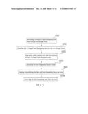
[0034]FIG. 5 is a diagram showing a method for fabricating a heat-dissipating base structure according to a second embodiment of the present invention;
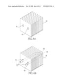
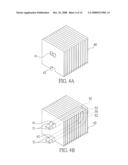
[0035]FIG. 6A is a diagram showing step (1) of the method for fabricating a heat-dissipating base structure according to a second embodiment of the present invention;
[0036]FIG. 6B is a diagram showing step (2) of the method for fabricating a heat-dissipating base structure according to a second embodiment of the present invention;
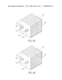
[0037]FIG. 6C is a diagram showing step (3) of the method for fabricating a heat-dissipating base structure according to a second embodiment of the present invention;
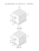
[0038]FIG. 6D is a diagram showing step (4) of the method for fabricating a heat-dissipating base structure according to a second embodiment of the present invention;
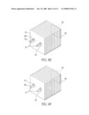
[0039]FIG. 6E is a diagram showing step (5) of the method for fabricating a heat-dissipating base structure according to a second embodiment of the present invention;
[0040]FIG. 6F is a diagram showing step (6) of the method for fabricating a heat-dissipating base structure according to a second embodiment of the present invention;
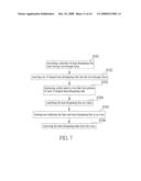
[0041]FIG. 7 is a diagram showing a method for fabricating a heat-dissipating base structure according to a third embodiment of the present invention;
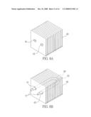
[0042]FIG. 8A is a diagram showing step (1) of the method for fabricating a heat-dissipating base structure according to a third embodiment of the present invention;
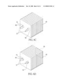
[0043]FIG. 8B is a diagram showing step (2) of the method for fabricating a heat-dissipating base structure according to a third embodiment of the present invention;
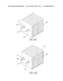
[0044]FIG. 8C is a diagram showing step (3) of the method for fabricating a heat-dissipating base structure according to a third embodiment of the present invention;
[0045]FIG. 8D is a diagram showing step (4) of the method for fabricating a heat-dissipating base structure according to a third embodiment of the present invention;
[0046]FIG. 8E is a diagram showing step (5) of the method for fabricating a heat-dissipating base structure according to a third embodiment of the present invention; and
[0047]FIG. 8F is a diagram showing step (6) of the method for fabricating a heat-dissipating base structure according to a third embodiment of the present invention.
DETAILED DESCRIPTION OF PREFERRED EMBODIMENTS
[0048]The following illustrative embodiments are provided to illustrate the disclosure of the present invention, these and other advantages and effects can be apparent to those skilled in the art after reading the disclosure of this specification. The present invention can also be performed or applied by other different embodiments. The details of the specification may be on the basis of different points and applications, and numerous modifications and variations can be made without departing from the spirit of the present invention.
[0049]FIG. 3 and FIGS. 4A to 4F are diagrams showing a method for fabricating a heat-dissipating base structure according to a first embodiment of the present invention. The method comprises the following steps.
[0050]At step S301, a plurality of heat-dissipating fins 40 are provided, each having at least an elliptic first through hole 41 and an elliptic second through hole 42 corresponding to the first through hole 41 and aligned in a vertical line. The first through hole 41 is formed on an upper side of the heat-dissipating fin 40 and the second through hole 42 is formed on a lower side of the heat-dissipating fin 40. The heat-dissipating fins 40 are parallel to each other, as shown in FIG. 4A. Then, the process goes to step S302.
[0051]At step S302, two U-shaped heat-dissipating tubes 50 are provided, each having two tube foot portions 51 and a bending portion 52. The diameter of the two tube foot portions 51 is smaller than diameter of the first through hole 41 at short edges and the two tube foot portions 51 are inserted into the first and second through holes 41, 42 respectively. In the present step, the U-shaped heat-dissipating tubes 50 are disposed at lower sides of the first and second through holes 41, 42, as shown in FIG. 4B. Then, the process goes to step S303.
[0052]At step S303, a dispensing tip (not shown) is penetrated into the spacing between the U-shaped heat-dissipating tubes 50 and the first and second through holes 41, 42 for dispensing, and solder paste 60 is coated to the two tube foot portions 51 of each U-shaped heat-dissipating tube 50. In the present embodiment, the solder paste 60 is coated on upper sides of the two tube foot portions 51 of the U-shaped heat-dissipating tubes 50, as shown in FIG. 4C. Then, the process goes to step S304.
[0053]At step S304, a base 30 is provided which has a surface for dispensing, and the parallel-aligned heat-dissipating fins 40 are mounted on the dispensed surface of the base 30. The U-shaped heat-dissipating tubes 50 are pressed toward the upper sides of the first and second through holes 41, 42, as shown in FIG. 4D. Then, the process goes to step S305.
[0054]At step S305, a clamp tool (not shown) is used to tighten the base 30 and the heat-dissipating fins to be placed in an oven (not shown) for heating and subsequent soldering, as shown in FIG. 4E. Then, the process goes to step S306.
[0055]At step S306, the heat-dissipating base is removed from the oven after the heating process, and after the heat-dissipating base cools off and is fixedly assembled the clamp tool is removed. As shown in FIG. 4F, a completed heat-dissipating base is shown.
[0056]In the first embodiment of the present invention, as the first and second through holes 41, 42 are vertically aligned, while the base 30 and the heat-dissipating fins 40 are assembled together, the U-shaped heat-dissipating tubes 50 can be tightened by the clamp tool and pressed toward the upper sides of the first and second through holes 41, 42. Thus, the U-shaped heat-dissipating tubes 50 are closely attached and soldered to the upper sides of the first and second through holes 41, 42. If the bending portions 52 of the U-shaped heat-dissipating tubes 50 lack sufficient strength for making the tube foot portions 51 closely attached to the upper sides of the first through holes 41, an additional clamp tool can be used for making the tube foot portions 51 closely attached to the upper side of the first through holes 41, which will be described later.
[0057]FIG. 5 and FIGS. 6A to 6F show a method for fabricating a heat dissipating base structure according to a second embodiment of the present invention, which comprises the following steps.
[0058]At step S501, a plurality of heat-dissipating fins 40 is provided, each has an elliptic first through hole 41 and an elliptic second through hole 42 corresponding to the first through hole 41, and the first and second through holes 41, 42 are aligned in a horizontal line. The first and second through holes 41, 42 are located at central positions of the heat-dissipating fins 40. The heat-dissipating fins 40 are parallel to each other, as shown in FIG. 6A. Then, the process goes to step S502.
[0059]At step S502, a U-shaped heat-dissipating tube 50 is provided, which has two tube foot portions 51 and a bending portion 52. The diameter of the two tube foot portions 51 is smaller than diameter of the first and second through holes 41, 42 at short edges and the two tube foot portions 51 are inserted into the first and second through holes 41, 42 respectively. In the present step, the U-shaped heat-dissipating tube 50 is disposed at lower sides of the first and second through holes 41, 42, as shown in FIG. 6B. Then, the process goes to step S503.
[0060]At step S503, a dispensing tip (not shown) is penetrated into the spacing between the U-shaped heat-dissipating tube 50 and the first and second through holes 41, 42 for dispensing, and solder paste 60 is coated to the two tube foot portions 51 of the U-shaped heat-dissipating tube 50. In the present embodiment, the solder paste 60 is coated on upper sides of the two tube foot portions 51 of the U-shaped heat-dissipating tube 50, as shown in FIG. 6C. Then, the process goes to step S504.
[0061]At step S504, a base 30 is provided which has a surface for dispensing, and the parallel-aligned heat-dissipating fins 40 are stack mounted on the dispensed surface of the base 30 through the bending portion 52 of the heat-dissipating tube 50, and a heat-dissipating tube clamp tool, which is a metal bar 70 in the present embodiment, is inserted into the spacing between the lower sides of the tube foot portions 51 of the U-shaped heat-dissipating tube 50 and the first and second through holes 41, 42 such that the two tube foot portions 51 can be pressed upward and closely attached to the first and second through holes 41, 42, as shown in FIG. 6D. Then, the process goes to step S505.
[0062]At step S505, a clamp tool (not shown) is used to tighten the base 30 and the heat-dissipating fins 40 to be placed in an oven (not shown) for heating and subsequent soldering, as shown in FIG. 6E. Then, the process goes to step S506.
[0063]At step S506, the heat-dissipating base is removed from the oven after the heating process, and after the heat-dissipating base cools off and is fixedly assembled the metal bar 70 is removed. As shown in FIG. 6F, a completed heat-dissipating base is shown.
[0064]In the second embodiment of the present invention, as the first and second through holes 41, 42 are horizontal aligned, while the base 30 and the heat-dissipating fins 40 are assembled together, the U-shaped heat-dissipating tube 50 cannot be tightened at the same time and therefore, a metal bar 70 is inserted into the spacing between the lower sides of the two foot tube portions 51 of the U-shape heat-dissipating tube 50 and the first and second through holes 41, 42 so as to press the U-shaped heat-dissipating tube 50 toward the upper sides of the first and second through holes 41, 42. Thus, the U-shaped heat-dissipating tube 50 is closely attached and soldered to the upper sides of the first and second through holes 41, 42.
[0065]FIG. 7 and FIGS. 8A to 8F show a method for fabricating a heat dissipating base structure according to a third embodiment of the present invention, which comprises the following steps.
[0066]At step S701, a plurality of heat-dissipating fins 40 is provided, each has an elliptic first through hole 41 and an elliptic second through hole 42 corresponding to the first through hole 41, the first and second through holes 41, 42 are horizontally arranged, and the major axes of the first and second through holes 41, 42 are in a horizontal line. The first through hole 41 and the second through hole 42 are located at central positions of the heat-dissipating fins 40. The heat-dissipating fins 40 are parallel to each other, as shown in FIG. 8A. Then, the process goes to step S702.
[0067]At step S702, a U-shaped heat-dissipating tube 50 is provided, which has two tube foot portions 51 and a bending portion 52. The diameter of the two tube foot portions 51 is smaller than diameter of the first and second through holes 41, 42 at short edges and the two tube foot portions 51 are inserted into the first and second through holes 41, 42 respectively. In the present step, the U-shaped heat-dissipating tube 50 is disposed at left sides of the first and second through holes 41, 42, as shown in FIG. 8B. Then, the process goes to step S703.
[0068]At step S703, a dispensing tip (not shown) is penetrated into the spacing between the U-shaped heat-dissipating tube 50 and the first and second through holes 41, 42 for dispensing, and solder paste 60 is coated to the two tube foot portions 51 of the U-shaped heat-dissipating tube 50. In the present embodiment, the solder paste 60 is coated to right sides of the two tube foot portions 51 of the U-shaped heat-dissipating tube 50, as shown in FIG. 8C. Then, the process goes to step S704.
[0069]At step S704, a base 30 is provided which has a surface for dispensing, and the parallel-aligned heat-dissipating fins 40 are stack mounted on the dispensed surface of the base 30 through the bending portion 52 of the heat-dissipating tube 50, and a heat-dissipating tube clamp tool, which is a metal bar 70 in the present embodiment, is inserted into the spacing between the left sides of the tube foot portions 51 of the U-shaped heat-dissipating tube 50 and the first and second through holes 41, 42 such that the two tube foot portions 51 can be pressed towards and closely attached to the right sides of the first and second through holes 41, 42, as shown in FIG. 8D. Then, the process goes to step S705.
[0070]At step S705, a clamp tool (not shown) is used to tighten the base 30 and the heat-dissipating fins 40 to be placed in an oven (not shown) for heating and soldering, as shown in FIG. 8E. Then, the process goes to step S706.
[0071]At step S706, the heat-dissipating base is removed from the oven after the heating process, and after the heat-dissipating base cools off and is fixedly assembled the heat dissipating base clamp tool and the metal bar 70 are removed. As shown in FIG. 8F, a completed heat-dissipating base is shown.
[0072]In the third embodiment of the present invention, as the first and second through holes 41, 42 are horizontal aligned and the major axes of the first and second through holes 41, 42 are in a horizontal line, while the base 30 and the heat-dissipating fins 40 are assembled together, the U-shaped heat-dissipating tube 50 cannot be tightened at the same time and therefore, a metal bar 70 is inserted into the spacing between the left sides (or right sides) of the two foot tube portions 51 of the U-shape heat-dissipating tube 50 and the first and second through holes 41, 42 so as to press the U-shaped heat-dissipating tube 50 toward the right sides of the first and second through holes 41, 42. Thus, the U-shaped heat-dissipating tube 50 is closely attached and soldered to the right sides of the first and second through holes 41, 42.
[0073]Compared with the conventional method for fabricating the heat-dissipating base structure, the connecting manner between the heat-dissipating fins and the heat-dissipating tubes of the present invention has a better soldering effect, thereby providing a heat-dissipating base structure having firm soldering connection, requiring less fabrication time and capable of providing enhanced heat-dissipating efficiency.
[0074]The above-described descriptions of the detailed embodiments are only to illustrate the preferred implementation according to the present invention, and it is not to limit the scope of the present invention. Accordingly, all modifications and variations completed by those with ordinary skill in the art should fall within the scope of present invention defined by the appended claims.
User Contributions:
comments("1"); ?> comment_form("1"); ?>Inventors list |
Agents list |
Assignees list |
List by place |
Classification tree browser |
Top 100 Inventors |
Top 100 Agents |
Top 100 Assignees |
Usenet FAQ Index |
Documents |
Other FAQs |
User Contributions:
Comment about this patent or add new information about this topic:
Images included with this patent application:
 |  |
 |  |
 |  |
 |  |
 |  |
 |  |
 |  |
 |
| Similar patent applications: | |
| Date | Title |
|---|---|
| 2012-10-11 | Method for fabricating heat dissipation substrate |
| 2012-11-08 | Method of forming a heat dissipating structure |
| 2010-06-24 | Method and system for fabricating roof trusses or similar structures |
| 2011-07-07 | Method for connecting heat-dissipating fin and heat pipe |
| 2010-02-11 | Method for fabricating blind via structure of substrate |
| New patent applications in this class: | |
| Date | Title |
|---|---|
| 2016-06-09 | Pin fin forming method |
| 2016-05-26 | Heat exchange reactor using thin plate provided with flow path therein and method of manufacturing the same |
| 2016-05-19 | Method of fabricating heat dissipating board |
| 2016-03-17 | Furnace burner box |
| 2016-02-11 | Method for manufacturing heat exchanger, and heat exchanger |
| New patent applications from these inventors: | |
| Date | Title |
|---|---|
| 2008-11-13 | Heat dissipating base structure |
| Top Inventors for class "Metal working" | |
| Rank | Inventor's name |
|---|---|
| 1 | Levi A. Campbell |
| 2 | Robert E. Simons |
| 3 | Branko Sarh |
| 4 | Richard C. Chu |
| 5 | Shou-Shan Fan |