Patent application title: PUMP HAVING HEAT-DISSIPATING MECHANISM
Inventors:
Xin-Hua Zhan (Foshan, CN)
Shao-Wen Pan (Foshan, CN)
Chun-Bo Chen (Foshan, CN)
IPC8 Class: AF01D508FI
USPC Class:
415177
Class name: Rotary kinetic fluid motors or pumps including heat insulation or exchange means (e.g., fins, lagging, etc.)
Publication date: 2008-12-18
Patent application number: 20080310954
Inventors list |
Agents list |
Assignees list |
List by place |
Classification tree browser |
Top 100 Inventors |
Top 100 Agents |
Top 100 Assignees |
Usenet FAQ Index |
Documents |
Other FAQs |
Patent application title: PUMP HAVING HEAT-DISSIPATING MECHANISM
Inventors:
Xin-Hua Zhan
Shao-wen Pan
Chun-bo Chen
Agents:
MOORE PATENTS
Assignees:
Origin: PALO ALTO, CA US
IPC8 Class: AF01D508FI
USPC Class:
415177
Abstract:
A pump includes a DC motor (10) defining a chamber (108) and having a
rotor (112) and a shaft (110) suitably received in the chamber, a motor
shell (20) set around the DC motor, a rear cover assembly (30) jointed to
the motor shell, a front cover assembly (40) secured to the rear cover
assembly, and a check valve assembly (50) and a diaphragm assembly (60)
set between the front cover assembly and the rear cover assembly. The DC
motor defines a number of air inlets (116) and air outlets (118) at two
side walls (104, 106) thereof, respectively. The shaft is equipped with a
rotatable fan (10). The motor shell has a number of ventilation holes
(200) in communication with the air outlets. The rear cover assembly
defines a number of through-holes (300) communicated to the air inlets.
The through-holes, the air inlets, the chamber, the air outlets and the
ventilation holes jointly define an air flow path. In operation, the fan
rotates around the shaft and forcibly circulates the air from the
through-holes and the air inlets out of the chamber via the air outlets
and the ventilation holes.Claims:
1. A pump comprising:a DC motor comprising a plurality of side walls
cooperatively defining a chamber, and a rotor and a shaft suitably
received in the chamber, the side walls being provided with a plurality
of air inlets and air outlets, and the shaft being equipped with a
rotatable fan;a motor shell set around the DC motor, the motor shell
defining a plurality of ventilation holes in communication with the air
outlets;a rear cover assembly securely coupled to the motor shell, the
rear cover assembly having a plurality of through-holes communicated to
the air inlets;a front cover assembly secured to the rear cover assembly;
anda check valve assembly and a diaphragm assembly set between the front
cover assembly and the rear cover assembly;wherein the through-holes, the
air inlets, the chamber, the air outlets and the ventilation holes
jointly define an airflow path, andduring operation of the pump, the fan
rotates around the shaft and forcibly circulates the air from the
through-holes and the air inlets out of the chamber via the air outlets
and the ventilation holes.
2. The pump as described in claim 1, wherein the DC motor comprises a front wall and a rear wall opposite to each other, the air inlets are defined in the front wall and the air outlets are disposed in the rear wall.
3. The pump as described in claim 2, wherein the fan is situated adjacent to the front wall of the DC motor.
4. The pump as described in claim 2, wherein the fan is located adjacent to the rear wall of the DC motor.
5. The pump as described in claim 1, wherein the through-holes are situated at a lower surface of the rear wall assembly and in communication with the air inlets defined in the DC motor.
6. The pump as described in claim 1, wherein the pump further comprises a pressure switch assembled to the front cover assembly thereof.
7. The pump as described in claim 1, wherein the diaphragm assembly comprises a bracket and a diaphragm detachably coupled to each other.
8. The pump as described in claim 7, wherein the diaphragm is coupled to the bracket via a plurality of screws.
9. The pump as described in claim 1, wherein the fan has an outer diameter compliant to an inner diameter of the chamber.
10. The pump as described in claim 1, wherein the fan is detachably coupled to the shaft.
Description:
CROSS-REFERENCE TO RELATED APPLICATIONS
[0001]The present application claims priority from Chinese Patent Application No. CN 200710028612.1, filed Jun. 15, 2007, which is incorporated by reference herein in its entirety.
FIELD OF THE INVENTION
[0002]The present invention generally relates to pumps and, more particularly, to a pump having heat-dissipating mechanism which can rapidly and effectively dissipate the heat generated during operation of the pump.
BACKGROUND OF THE INVENTION
[0003]In general, pumps are widely used in various devices, for instance agricultural spraying equipment, cleaning machines and beverage accessories, to transport fluid or liquid to a predetermined site.
[0004]A conventional pump typically includes a front cover assembly, a check valve assembly, a diaphragm assembly, a rear cover assembly, a direct current motor (DC motor) and a motor shell enclosing the DC motor sequentially coupled to each other. In operation, the DC motor drives a bracket of the pump to move axially, so as to change the volumes of a number of isolated and sealed cavities close to the bracket. When the volume of the sealed cavity increases, the fluid is sucked in. When the volume of the sealed cavity decreases, the fluid or the liquid in the cavity is discharged.
[0005]Pumps generally work under high pressure for a long period of time. During operation, the DC motor will generate a considerable amount of heat. The heat generated in the DC motor must be transferred to the external surroundings, so as to maintain optimum operation of the DC motor. However, in conventional pumps, the heat generated is transferred to the surroundings via heat conduction of the side walls of the DC motor. This conductive transfer of heat to the surroundings is inefficient and, therefore, the heat generated by the DC motor must be actively removed to avoid motor overheating. Otherwise, the accumulated heat may not only lead to poor performance of the pump, but also may result in potential early burn-out of the DC motor.
[0006]To timely and effectively dissipate the heat of the DC motor, an external fan is provided to forcibly remove the heat from the motor shell set around the DC motor. However, this approach requires a high heat conducting performance of the material of the motor shell and results in high manufacturing costs. Moreover, the usual heat conduction through the motor shell still may not be satisfactory to avoid DC motor overheating and possible early burn-out.
[0007]Additionally, the conventional design of a diaphragm assembly for the pump is configured to have a diaphragm and a bracket securely and permanently fixed to each other. Once assembled, the bracket and the diaphragm cannot be disassembled from each other without being destroyed. Therefore, when one element of the diaphragm assembly, i.e. diaphragm or the bracket, does not function properly during operation, the whole diaphragm assembly must be replaced. Neither the diaphragm nor the bracket can be reused, which contributes to high pump maintenance costs.
SUMMARY OF THE INVENTION
[0008]It is therefore one object of the present invention to provide a pump having a heat-dissipating mechanism, which can rapidly and effectively remove the heat generated during operation of the pump.
[0009]It is still another object of the present invention to provide a pump having a readily replaceable diaphragm assembly, which can economically facilitate replacement of the diaphragm assembly and reduce pump maintenance costs.
[0010]According to one preferred embodiment of the present invention, a pump includes a DC motor defining a chamber and having a rotor and a shaft suitably received in the chamber, a motor shell set around the DC motor, a rear cover assembly joined to the motor shell, a front cover assembly secured to the rear cover assembly, and a check valve assembly and a diaphragm assembly sandwiched between the front cover assembly and the rear cover assembly. The DC motor defines a number of air inlets and air outlets at two side walls thereof, respectively. The shaft is equipped with a rotatable fan. The motor shell has a number of ventilation holes in communication with the air outlets. The rear cover assembly defines a number of through-holes communicated to the air inlets. The through-holes, the air inlets, the chamber, the air outlets and the ventilation holes jointly define an airflow path. In operation, the fan rotates around the shaft and forcibly circulates the air from the through-holes and the air inlets out of the chamber via the air outlets and the ventilation holes and, therefore, removes the heat generated in operation of the pump effectively and timely.
[0011]According to another embodiment of the present invention, a diaphragm assembly of the pump includes a diaphragm and a bracket detachably coupled to each other, for instance via a number of screws. Therefore, during maintenance, if one element of the diaphragm assembly, i.e. the diaphragm or the bracket, malfunctions, only the relevant malfunctioning element needs to be replaced. There is no need to replace the whole diaphragm assembly and, thus, the maintenance cost of the pump can be reduced remarkably.
[0012]Other advantages and novel features will be drawn from following detailed description of preferred embodiments with the attached drawings, in which:
BRIEF DESCRIPTION OF THE DRAWINGS
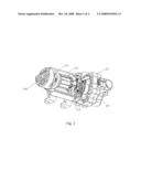
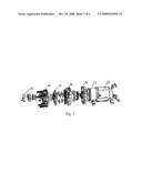
[0013]FIG. 1 depicts an exploded, isometric view of a pump in accordance with one preferred embodiment of the present invention;
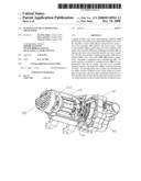
[0014]FIG. 2 depicts an assembled, isometric view of the pump as illustrated in FIG. 1, wherein part of the motor shell is removed to show the inner structure of the pump;
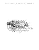
[0015]FIG. 3 depicts a cross-sectional view of the pump shown in FIG. 2, wherein an arrowed line is used to show the airflow path during the operation of the pump; and
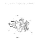
[0016]FIG. 4 depicts an enlarged, exploded view of the diaphragm assembly shown in FIG. 1.
DETAILED DESCRIPTION OF THE INVENTION
[0017]Referring to FIGS. 1 to 3, a pump according to a preferred embodiment of the present invention includes a DC motor 10, a motor shell 20 enclosing the DC motor 10, a rear cover assembly 30 coupled to the motor shell 20, a front cover assembly 40 attached to the rear cover assembly 30, a check valve assembly 50 and a diaphragm assembly 60 sandwiched between the front cover assembly 40 and the rear cover assembly, and a pressure switch 70 assembled to the front cover assembly 40.
[0018]The DC motor 10 is substantially sealed and includes a columniform side wall 102 and a front wall 104 and an opposing rear wall 106. The side wall 102, the front wall 104 and the rear wall 106 jointly enclose a chamber 108 to suitably receive a shaft 110 and a rotor 112 therein.
[0019]The shaft 110 of the DC motor 10 is equipped with a fan 114 detachably assembled thereto. The fan 114 has an outer diameter in conformity with the inner diameter of the chamber 108, to rotate with the shaft 110 in the chamber 108 freely. The fan 114 is positioned adjacent to the front wall 104 of the DC motor 10. In an alternative embodiment of the present invention, the fan 114 can also be situated adjacent to the rear wall 106 of the DC motor 10. The fan 114 rotates with the rotation of the shaft 110, so that the air in the chamber 108 flows smoothly from the front wall 104 to the rear wall 106.
[0020]The front wall 104 has a number of air inlets 116 evenly distributed therein. The air inlets 116 are connected to chamber 108 and through-holes 300 in the rear cover assembly 30. The rear wall 106 is correspondingly provided with a number of air outlets 118 evenly situated in the rear wall 106 and in direct communication with the chamber 108.
[0021]In order to dissipate the heat generated by the DC motor 10 more effectively, the motor shell 20 preferably includes a number of ventilation holes 200 corresponding to the air outlets 118. The ventilation holes 200 are in communication with the air outlets 118, so that the air from the chamber 108 can be removed to the surroundings directly.
[0022]The rear cover assembly 30 is arranged with a number of through-holes 300 corresponding to the air inlets 116 defined in the front wall 104 of the DC motor 10. The through-holes 300, the air inlets 116, the chamber 108 of the DC motor 10, the air outlets 118 and the ventilation holes 20 cooperatively define an airflow path.
[0023]As a preferred embodiment of the present invention, the through-holes 300 are preferably provided at a lower surface of the rear cover assembly 30, so that fluid or liquid cannot penetrate into the DC motor 10.
[0024]Referring particularly to FIG. 4, the diaphragm assembly 60 includes a diaphragm 600 and a bracket 602. The diaphragm 600 and the bracket 602 each define a number of holes (not labeled) in alignment with each other. A plug 606 and holders 608 each having a number of mounting holes (not labeled) are located at two sides of the diaphragm 600 and the bracket 602. The plug 606 and the holders 608 can be compliantly inserted to the holes of the diaphragm 600 and the bracket 602, such that the diaphragm 600 and the bracket 602 can be detachably coupled together via a number of screws 610. Therefore, the diaphragm assembly 60 can be easily assembled and disassembled. Additionally, the diaphragm 600 and the bracket 602 can also be detachably assembled to each other via other known means in the art, such as a board lock-like mechanism.
[0025]Referring particularly to FIG. 1 and FIG. 2, in assembly, the shaft 110 coupled with the fan 114 and the rotor 112 is compliantly positioned in the chamber 108. The DC motor 10 is securely set within the motor shell 20, with the air outlets 118 in the rear wall 106 of the DC motor 10 corresponding to the ventilation holes 200 of the motor shell 20. The rear cover assembly 30 is assembled to the motor shell 20, with the through-holes 300 in the rear cover assembly 20 in alignment with the air inlets 116 in the front wall 104 of the DC motor. The check valve assembly 50 and the diaphragm assembly 60 detachably coupled by the screws 610 are interposed between the rear cover assembly 30 and coupled to the rear cover assembly 30 in turn. The front cover assembly 40 is suitably coupled to the rear cover assembly 30. The pressure switch 70 is properly coupled to the front cover assembly 40, so as to control the pressure of the pump.
[0026]After assembly, the through-holes 300 in the rear cover assembly 30, the air inlets 116 in the front wall 104 of the DC motor 10, the chamber 108 of the DC motor 10, the air outlets 118 in the rear wall 106 of the DC motor 10 and the ventilation holes 200 in the motor shell 20 jointly define an airflow path.
[0027]Referring particularly to FIG. 3, in operation, the shaft 110 of the DC motor 10 drives the fan 114 to rotate. The cool air from the surroundings enters the chamber 108 of the DC motor via the through-holes 300 of the rear cover assembly 30 and the air inlets 116 in the front wall 104 of the DC motor 10. Driven by the fan 114, the cool air passes through the rotor 112 of the DC motor 10 and flows out of the chamber 108 to the surroundings via the air outlets 118 in the rear wall 106 of the DC motor 10 and the ventilation holes 300 in the motor shell 20. Therefore the heat generated during operation of the DC motor 10 can be dissipated to the surroundings efficiently, so as to keep the temperature in the chamber 108 at a desirable level and ensure the stability of the DC motor 10.
[0028]Additionally, if one element of the diaphragm assembly 60, i.e. the diaphragm 600 or the bracket 602 malfunctions during operation, the diaphragm assembly 60 can be disassembled from the pump. Thereafter, the relevant element of the diaphragm assembly 60 can be replaced. Therefore, there is no need to replace the whole diaphragm assembly 60, and the maintenance costs of the pump can be considerably reduced.
[0029]While the present invention has been illustrated by the above description of the preferred embodiments thereof, and while the preferred embodiments have been described in considerable detail, it is not intended to restrict or in any way limit the scope of the appended claims to such details. Additional advantages and modifications within the spirit and scope of the present invention will readily appear to those skilled in the art. Therefore, the present invention is not limited to the specific details and the illustrative examples shown and described.
User Contributions:
comments("1"); ?> comment_form("1"); ?>Inventors list |
Agents list |
Assignees list |
List by place |
Classification tree browser |
Top 100 Inventors |
Top 100 Agents |
Top 100 Assignees |
Usenet FAQ Index |
Documents |
Other FAQs |
User Contributions:
Comment about this patent or add new information about this topic:
Images included with this patent application:
 |  |
 |  |
 |
| Similar patent applications: | |
| Date | Title |
|---|---|
| 2010-08-12 | Multilayer shielding ring for a flight driving mechanism |
| 2008-09-11 | Fan with heat dissipating outlet guide vanes |
| 2009-03-05 | Pumps and pump-heads comprising internal pressure-absorbing member |
| 2008-10-02 | Expansion turbine having a variable nozzle mechanism |
| 2008-10-02 | Expansion turbine having a variable nozzle mechanism |
| New patent applications in this class: | |
| Date | Title |
|---|---|
| 2019-05-16 | Dendritic heat exchangers and methods of utilizing the same |
| 2018-01-25 | Multi-ply heat shield assembly with integral band clamp for a gas turbine engine |
| 2017-08-17 | Turbine stator vane with closed-loop sequential impingement cooling insert |
| 2016-12-29 | Fan module and hat with fan module |
| 2016-12-29 | Low loss baffled serpentine turns |
| Top Inventors for class "Rotary kinetic fluid motors or pumps" | |
| Rank | Inventor's name |
|---|---|
| 1 | Gabriel L. Suciu |
| 2 | Frederick M. Schwarz |
| 3 | United Technologies Corporation |
| 4 | Brian D. Merry |
| 5 | Craig M. Beers |