Patent application title: Bucket divider for tool transport
Inventors:
Glenn Summerfield (Manasquan, NJ, US)
IPC8 Class: AB65D2504FI
USPC Class:
220529
Class name: Receptacles compartmented container compartment partition is movable or removable
Publication date: 2008-12-18
Patent application number: 20080308560
Inventors list |
Agents list |
Assignees list |
List by place |
Classification tree browser |
Top 100 Inventors |
Top 100 Agents |
Top 100 Assignees |
Usenet FAQ Index |
Documents |
Other FAQs |
Patent application title: Bucket divider for tool transport
Inventors:
Glenn Summerfield
Agents:
CLIFFORD G. FRAYNE
Assignees:
Origin: BRICK, NJ US
IPC8 Class: AB65D2504FI
USPC Class:
220529
Abstract:
A transport assembly for hand tools and small hardware items, including a
bucket having a side wall, a plurality of partition dividers, each
partition divider having an end wall angled cooperable with the angle of
the side wall of the bucket, the lower longitudinal edge of each
partition divider having a length equal to the inner diameter of the
bucket at its lowest point, and also having rounded lower corners, each
of the partition dividers having a plurality of partial vertical slits
formed therein and aligned with parallel ridges on each side of the
partition, the ridges spaced apart the width of the slit, thereby
permitting the partition dividers to slidably interlock with each other
to form a honeycomb arrangement defining a plurality of segmented
cavities within the bucket for the storage, transport and retrieval of
hand tools and small hardware items.Claims:
1. A bucket with removable divider for transport of tools or small
hardware items comprising:a bucket chamber defined by a planar bottom
wall, upstanding outwardly tapered side wall terminating in an upper
circular periphery, there being an arcuate handle member spanning said
upper circular periphery;a removable divider insert receivable within
said bucket chamber, said removable divider insert comprising a plurality
of lower partition dividers interlocking with a plurality of upper
partition dividers to define a plurality of partitioned segregated spaces
within said bucket chamber for the receipt of tools, or small hardware
items, said lower partition divider having a planar first side wall and
planar second side wall, said first and second side walls terminating in
upwardly, outwardly tapered end edges conforming to said outward taper of
said side wall of said bucket chamber, said lower partition dividers have
depending from an upper edge, a plurality of vertical slits extending
halfway between said upper edge and a lower edge of said lower partition
divider, said lower partition divider further having a plurality of
parallel ridges extending upwardly from said lower edge of said lower
partition divider to the terminus of said downwardly depending slits,
said parallel ridges spaced apart the width of said downwardly depending
slits;said upper partition divider defined by a planar first side wall
and planar second side wall terminating in two end edges tapered upwardly
and outwardly from a lower edge to an upper edge of said upper partition
divider to conform to said side wall of said bucket chamber, said upper
partition divider having a plurality of upwardly extending vertical slits
from said lower edge terminating halfway between said lower edge and said
upper edge, said upper partition divider having a plurality of depending
vertical parallel ridges extending downwardly from said upper edge to the
terminus of said upwardly extending slits, said parallel ridges spaced
apart a distance equal to the width of said upwardly depending slits,
said plurality of lower partition dividers and said plurality of upper
partition dividers interlocking by means of said slits and said parallel
ridges to form a plurality of partition spaces within said bucket defined
by said upper and lower partition dividers and said side wall of said
bucket chamber.
2. The bucket with removable divider for transport of tools or small hardware items in accordance with claim 1 wherein said side walls of said lower partition divider and said upper partition divider are frictionally engaged with said tapered side wall of said bucket chamber.
3. The bucket with removable divider for transport of tools or small hardware items in accordance with claim 1 wherein said intersection of said end edges with said lower edge of said lower partition divider and said upper partition divider are shaped to conform to the intersection of said planar bottom wall and said upstanding outwardly tapered side wall of said bucket chamber.
Description:
RELATED APPLICATIONS
[0001]Applicant claims the benefit of provisional application 60/934,489, filed Jun. 14, 2007.
BACKGROUND OF THE INVENTION
[0002]1. Field of the Invention
[0003]The present invention relates to the transportation of hand tools and small hardware items, and more particularly, to a divider apparatus cooperable with a bucket for dividing the interior of the bucket into segmented cavities for the receipt of individual hand tools or small hardware items.
[0004]2. Description of the Prior Art
[0005]Many handyman jobs around the house or office normally require the use of several different hand tools and small hardware items such as fasteners or the like. It is not often convenient to transport a heavy tool box from site to site in order to perform repairs or perform tasks. Normally the individual will have a fair idea of the tools necessary to perform the repair or task and will choose only those tools required. The difficulty arises in transporting those tools from site to site.
[0006]Tool belts are a handy item for such transport, but are not always available to a homeowner. A bucket is normally available and handy and tools can be placed in the bucket for transport, however, the drawback with the bucket transport is that the plurality of tools being transported are interspersed within the bucket and not easily identified and grasped when performing the repair or task.
[0007]This problem has been addressed in the prior art by Darrey in U.S. Pat. No. 5,350,065, Varnom in U.S. Pat. No. 5,836,446, and Morse in U.S. Pat. No. 7,159,735. However, in each of these instances, the solution has been a lid-like element having apertures therein which allow the tools to hang in the holes so that the tools extend upwardly above the bucket lid. Morse developed a bucket insert having a plurality of round apertures and an upper support member and a lower support member which would support the tools in an upright position.
[0008]Applicant has developed a simpler solution which allows for the transport and segregation of tools and small hardware items of varying shapes and sizes and allows the user to quickly identify and retrieve the tool from the bucket.
OBJECTS OF THE INVENTION
[0009]An object of the present invention is to provide for a novel bucket and insert for the segmentation of the bucket into discrete cavities for the storage, transport, and retrieval of hand tools and small hardware items.
[0010]A still further object of the present invention is to provide for a novel insert for segmenting the interior of a bucket into discrete cavities for the storage, transport and retrieval of hand tools and small hardware items, which insert is formed with interlocking members.
[0011]A still further object of the present invention is to provide for a novel insert for a bucket for the storage, transport and retrieval of hand tools and small hardware items in which the outwardly extending ends of the insert members are angled so as to frictionally engage and cooperate with the angled inner side wall of a bucket.
SUMMARY OF THE INVENTION
[0012]A transport assembly for hand tools and small hardware items, including a bucket having a side wall, a plurality of partition dividers, each partition divider having an end wall angled cooperable with the angle of the side wall of the bucket, the lower longitudinal edge of each partition divider having a length equal to the inner diameter of the bucket at its lowest point, and also having rounded lower corners, each of the partition dividers having a plurality of partial vertical slits formed therein and aligned with parallel ridges on each side of the partition, the ridges spaced apart the width of the slit, thereby permitting the partition dividers to slidably interlock with each other to form a honeycomb arrangement defining a plurality of segmented cavities within the bucket for the storage, transport and retrieval of hand tools and small hardware items.
BRIEF DESCRIPTION OF THE DRAWINGS
[0013]These and other objects of the present invention will become apparent, particularly when taken in light of the following illustrations wherein:
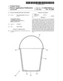
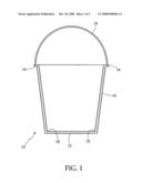
[0014]FIG. 1 is a cutaway view of a typical bucket for use with the present invention;
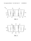
[0015]FIG. 2 is a planar side view of a first type of partition divider;
[0016]FIG. 3 is a planar side view of a second type of partition divider;
[0017]FIG. 4 is a perspective view of the first type of partition divider;
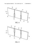
[0018]FIG. 5 is a perspective view of the second type of partition divider;
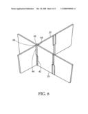
[0019]FIG. 6 is a perspective view of a portion of the assembled partition dividers; and
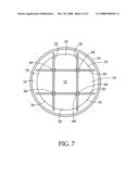
[0020]FIG. 7 is a top view of a bucket with the assembled partition dividers secured therein.
DETAILED DESCRIPTION OF THE INVENTION
[0021]FIG. 1 is a cutaway view of a typical bucket 10 for use with the present invention. Bucket 10 comprises a generally planar bottom wall 12 integrally formed with an upstanding side wall 14 terminating with a peripheral lip 16. Side wall 14 normally tapers outwardly between bottom wall 12 and peripheral lip 16. Since bottom wall 12 and side wall 14 are unitarily formed or molded, the intersection 18 of bottom wall 12 and side wall 14 arcuate or rounded. Bucket 10 typically has a handle means 19 secured either to side wall 14 or to peripheral lip 16.
[0022]FIGS. 2 and 4 are a planar and perspective view of a first type of partition divider identified as the lower partition divider 20 and FIGS. 3 and 5 are a planar and perspective view of a second type of partition divider referred to as the upper partition divider 22.
[0023]Lower partition divider 20 is generally planar having a first side wall 24 and a second side wall 26. The end edges 28 and 30 of lower partition divider 20 are angled outwardly from bottom edge 32 to upper edge 34 in order to conform to the inner taper of bucket 10. Still further, the bottom edge corners 36 and 38 where bottom edge 32 intersects with end edges 28 and 30 is rounded to conform to the arcuate or rounded intersection of bottom wall 12 and side wall 14 of bucket 10. Still further, end edges 28 and 30 are slightly arcuate (See FIG. 7) to cooperate with the curvature of the inner surface of side wall 14 of bucket 10.
[0024]Depending from upper edge 34 of lower partition divider 20 are a plurality of vertical slits 40 which extend approximately half way between upper edge 34 and lower edge 32. In the embodiment illustrated, there are two such slits. Also formed on the side walls 24 and 26 of lower partition 20 are a pair of parallel ridges 42. Parallel ridges 42 are set apart in equal distance to the width of slits 40 and extend from the termini of slits 40 to the lower edge 32 of lower partition divider 20 on both side walls 24 and 26.
[0025]FIGS. 3 and 5 are a planar and a perspective view of the upper partition divider 22. It is formed with two planar side walls 50 and 52 and upper edge 54, a bottom edge 56, and two end edges 58 and 60. End edges 58 and 60 of upper partition divider 22 are tapered inwardly from upper edge 54 to lower edge 56 and the intersection of lower edge 56 with end edges 58 and 60 is rounded to conform with the arcuate or rounded intersection of bottom wall 12 and side wall 14 of bucket 10. The end edges 58 and 60 are also slightly arcuate between side walls 50 and 52 (See FIG. 7) to cooperate with the curvature of the inner surface of side wall 14 of bucket 10. Upper partition divider 20 has a plurality of upwardly extending vertical slits 62 commencing at lower edge 56 and terminating halfway between lower edge 56 and upper edge 54. Also formed on the planar side walls 50 and 52 of upper partition divider 22 are pairs of vertical ridges 64 spaced apart the distance of the width of the slits 62, parallel ridges being formed on both sides of the planar side walls.
[0026]FIG. 6 is a perspective view of a portion of the assembled partition dividers 20 and 22. Lower partition dividers 20 are spaced in parallel vertical relationship and upper partition dividers 22 are engaged with the lower partition dividers 20 by aligning and sliding the slits 62 extending upwardly from lower edge 56 of the upper partition divider 22 into the space between the parallel ridges 42 on lower partition divider 20 which simultaneously causes the non-slit portion of upper partition divider 22 to be engaged in the upwardly extending slits 40 of lower partition divider 20.
[0027]In the instant embodiment, two lower partition dividers 20 and two upper partition dividers 22 are utilized to form the assembly. Parallel ridges 42 and 64 add stability to the assembly by preventing any wobble or angular displacement of the upper partition dividers 22 in relationship to the lower partition dividers 20.
[0028]FIG. 7 is a top view of a bucket with the assembled partition dividers 20 and 22 of FIG. 4 secured therein. Since the partition dividers 20 and 22 have been dimensioned to the inner dimensions of bucket 10, the bottom edges 32 and 56 of lower partition divider 20 and upper partition divider 22 engage the bottom wall 12 of bucket 10. The angled end edges 28 and 30 of lower partition divider 20 and 58 and 60 upper partition divider 22 conform to the taper of the bucket 10 and are thus frictionally engaged with the side wall 14 of bucket 10. The cooperation of the slits and parallel ridges on both upper partition divider 22 and lower partition divider 20 in cooperation with the end edges in intimate contact with the side walls of bucket 10 ensures the integrity of the assembly. In the embodiment shown, two upper partition dividers 22 and two lower partition dividers 20 have been utilized with bucket 10 to define an assembly which defines nine separate cavities 70 within bucket 10. Each cavity will be capable of receiving, storing and transporting at least one hand tool or multiple small hardware items.
[0029]The height of the lower partition divider 20 and the upper partition divider 22 would be one of choice. The height would be sufficient to maintain segregation of the various hand tools positioned in the various cavities 70, yet still be below the peripheral lip 16 of bucket 10 and still allow the user to identify and retrieve a selected item when desired.
[0030]Therefore, while the present invention has been disclosed with respect to the preferred embodiments thereof, it will be recognized by those of ordinary skill in the art that various changes and modifications can be made without departing from the spirit and scope of the invention. It is therefore manifestly intended that the invention be limited only by the claims and the equivalence thereof.
User Contributions:
comments("1"); ?> comment_form("1"); ?>Inventors list |
Agents list |
Assignees list |
List by place |
Classification tree browser |
Top 100 Inventors |
Top 100 Agents |
Top 100 Assignees |
Usenet FAQ Index |
Documents |
Other FAQs |
User Contributions:
Comment about this patent or add new information about this topic:
| People who visited this patent also read: | |
| Patent application number | Title |
|---|---|
| 20170173585 | POINT OF CARE POLYMERASE CHAIN REACTION DEVICE FOR DISEASE DETECTION |
| 20170173584 | DEVICE FOR MANIPULATION OF PACKETS IN MICRO-CONTAINERS, IN PARTICULAR IN MICROCHANNELS |
| 20170173583 | LIQUID HANDLING DEVICE |
| 20170173582 | MICROFLUIDIC DEVICE AND CONTROL EQUIPMENT FOR MICROFLUIDIC DEVICE |
| 20170173581 | Film Bag for a Microfluidic Analysis System, Microfluidic Analysis System, Method for Producing and Method for Operating a Microfluidic Analysis System |
Images included with this patent application:
 |  |
 |  |
 |  |
| Similar patent applications: | |
| Date | Title |
|---|---|
| 2012-03-22 | Unit load device and container for transporting cargo |
| 2009-11-12 | Container for storage and transport of liquids |
| 2011-09-15 | Modular cartridge for liquid transport |
| 2012-01-12 | Container for produce storage, packing & transport |
| 2008-12-18 | Bucket tool organizer with tool insert |
| New patent applications in this class: | |
| Date | Title |
|---|---|
| 2016-12-29 | Hinged one piece divider for container assembly |
| 2016-05-19 | Segregated receptacle |
| 2016-04-14 | Inventory supply system and methods of use |
| 2016-01-07 | Hygienic laundry basket |
| 2015-12-17 | Apparatus, system and methods for a fold down multiple cavity divider |
| New patent applications from these inventors: | |
| Date | Title |
|---|---|
| 2009-01-22 | Anchor for screw fastener |
| 2008-11-27 | Gripping sleeve |
| Top Inventors for class "Receptacles" | |
| Rank | Inventor's name |
|---|---|
| 1 | Daniel Lee Bizzell |
| 2 | Frank Yang |
| 3 | Terry Vovan |
| 4 | William P. Apps |
| 5 | Lowell L. Wood, Jr. |