Patent application title: Electrical connector having improved housing
Inventors:
Fu-Pin Hsieh (Tu-Cheng, TW)
Fu-Pin Hsieh (Tu-Cheng, TW)
IPC8 Class: AH05K712FI
USPC Class:
361810
Class name: For electronic systems and devices component mounting or support means plural mounting or support
Publication date: 2008-12-11
Patent application number: 20080304244
Inventors list |
Agents list |
Assignees list |
List by place |
Classification tree browser |
Top 100 Inventors |
Top 100 Agents |
Top 100 Assignees |
Usenet FAQ Index |
Documents |
Other FAQs |
Patent application title: Electrical connector having improved housing
Inventors:
Fu-Pin Hsieh
Agents:
WEI TE CHUNG;FOXCONN INTERNATIONAL, INC.
Assignees:
Origin: SANTA CLARA, CA US
IPC8 Class: AH05K712FI
USPC Class:
361810
Abstract:
An electrical connector (1) is adapted for electrically connecting an
electronic package (3) to a circuit board (4). The electrical connector
includes a housing (5) having a number of contacts retained therein, a
number of hook portions (24) rising from the housing and resisting
against an upper surface of the electronic package for fastening the
electronic package to the housing.Claims:
1. An electrical connector adapted for electrically connecting an
electronic package to a circuit board, comprising:a housing having a
plurality of contacts retained therein, a plurality of hook portions
rising from the housing and resisting against an upper surface of the
electronic package for fastening the electronic package to the housing.
2. The electrical connector as claimed in claim 1, wherein each hook portion has an obliquely extending guiding face guidable of the electronic package.
3. The electrical connector as claimed in claim 2, wherein said housing comprises four housing units arranged as a rectangular shape and a rectangular opening encircled by the four housing units.
4. The electrical connector as claimed in claim 3, wherein said hook portions are symmetrically formed at opposite ends of an outer edge of each housing unit.
5. The electrical connector as claimed in claim 2, wherein said housing is formed as a rectangular flat board, and the hook portions extend upwardly from a middle portion of each side edge of the housing.
6. An electrical connector assembly comprising:a plurality of insulative housing units arranged along a periphery of a receiving area; andan IC package being configured to be essentially compliant with said receiving area and mounted upon said housing units; whereineach of said housing units defines at least a deflectable latch under a condition that the latches of the different housing units engage different sides of said IC package, respectively.
7. The electrical connector assembly as claimed in claim 6, wherein each of said housing units is equipped with two said latches at two opposite ends of the housing units, respectively.
Description:
BACKGROUND OF THE INVENTION
[0001]1. Field of the invention
[0002]The present invention relates to an electrical connector, and particularly to an electrical connector electrically connecting an electronic package such as an IC package to a circuit board.
[0003]2. Description of Related Art
[0004]An electrical connector comprises a housing having a plurality of contacts, a stiffener surrounding the housing and formed with an engaging portion, a cover rotatably mounted on the housing and having a tongue portion, and a lever engaging with the tongue portion of the cover. When an IC package is positioned on the housing, the cover is rotated to a closed position and fasten the IC package at the closed position via an engagement between the lever and the engaging portion.
[0005]The IC package could be fixed in the stiffener, under the operation of the lever and the cover. It is complicated to assemble the cover and lever onto the housing. Simultaneously, it would take great space to position the lever and the cover.
[0006]Hence, an improved electrical connector is required to overcome the above-mentioned disadvantages of the related art.
SUMMARY OF THE INVENTION
[0007]An object of the present invention is to provide an electrical connector taking less space and easy to assemble.
[0008]To achieve the aforementioned objects, an electrical connector is adapted for electrically connecting an electronic package to a circuit board. The electrical connector includes a housing having a number of contacts retained therein, a number of hook portions rising from the housing and resisting against an upper surface of the electronic package for locking the electronic package to the housing.
[0009]The hook portions extend upwardly from the housing for fastening the IC package in the housing. It is not necessary to assemble a fastening mechanism on the housing to fasten the IC package. The housing together with the hook portions would not occupy extra space.
[0010]Other objects, advantages and novel features of the invention will become more apparent from the following detailed description of a preferred embodiment when taken in conjunction with the accompanying drawings.
BRIEF DESCRIPTION OF THE DRAWINGS
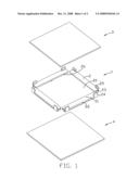
[0011]FIG. 1 is an exploded perspective view of an electrical connector in accordance with the present invention; and
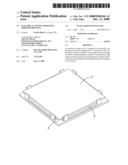
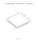
[0012]FIG. 2 is an assembled perspective view of the electrical connector as shown in FIG. 1.
DETAILED DESCRIPTION OF THE INVENTION
[0013]Reference will now be made to the drawing figures to describe the present invention in detail. Referring to FIGS. 1-2, an electrical connector 1 in accordance with the preferred embodiment of the present invention comprises a housing 5 electrically connecting an IC package 3 to a circuit board 4.
[0014]Referring to FIG. 1, the housing 5 comprises four separated rectangular housing units 2. Each housing unit 2 comprises a body portion 21 defining a plurality of slots (not shown) for receiving a plurality of power contacts (not shown), an outer wall 22 and an inner wall 26 extending along two opposite longitudinal edges of the body portion 21, and a pair of connecting walls 23 formed at another two opposite edges of the body portion 21. Each outer wall 22 of the housing unit 2 is symmetrically formed with a pair of hook portions 24 rising from two opposite ends thereof for engaging with the IC package 3. Each hook portion 24 has a inclined guiding face 25 formed at an top portion thereof for guiding the IC package 3.
[0015]In assembly of the electrical connector 100, the four housing units 2 are arranged as a rectangular shape to form the insulative housing 5 and soldered on the circuit board 4 firstly, with a substantially rectangular opening 20 encircled by the four housing units 2 and the inner walls 26 facing toward the opening 20. A signal connector (not shown) is received in the opening 20. The IC package 3 is guided toward the opening 20 along the guiding faces 25 and resisted against by the hook portions 24. Finally, the IC package 3 is firmly fastened to the insulative housing 5 to thereby establish a reliable electrical connection between the IC package 3 and the signal connector.
[0016]Optionally, the insulative housing 5 could be integrally formed as a rectangular flat board. The hook portions 24 could be provided at a middle portion of the four edges of the insulative housing 5 for resisting against the upper surface of the IC package 3.
[0017]The hook portions 25 extend upwardly from the housing for fastening the IC package 3 in the housing 5. It is not necessary to assemble a fastening mechanism to fasten the IC package 3. The housing 5 together with the hook portions 25 would not occupy extra space.
[0018]However, the disclosure is illustrative only, changes may be made in detail, especially in matter of shape, size, and arrangement of parts within the principles of the invention.
User Contributions:
comments("1"); ?> comment_form("1"); ?>Inventors list |
Agents list |
Assignees list |
List by place |
Classification tree browser |
Top 100 Inventors |
Top 100 Agents |
Top 100 Assignees |
Usenet FAQ Index |
Documents |
Other FAQs |
User Contributions:
Comment about this patent or add new information about this topic:
Images included with this patent application:
 |  |
 |
| Similar patent applications: | |
| Date | Title |
|---|---|
| 2010-04-08 | Helical conduit enabled for casting inside a housing |
| 2012-05-17 | Electrostatic discharge conducting pathway having a noise filter spark gap |
| 2012-05-24 | Electrical system, and electrical switching apparatus and shutter assembly therefor |
| 2012-05-17 | Flexible circuit assemblies with stacked flex interconnects and connector assemblies having the same |
| 2012-05-24 | Electronic apparatus with improved heat dissipation |
| New patent applications in this class: | |
| Date | Title |
|---|---|
| 2016-07-14 | Display apparatus |
| 2016-04-14 | Operating control unit for an electrical appliance and electrical appliance |
| 2014-10-09 | Power converter designed to minimize mechanical vibration of converter component |
| 2014-06-12 | Mounting apparatus for battery module |
| 2014-06-12 | Battery backup cover system |
| New patent applications from these inventors: | |
| Date | Title |
|---|---|
| 2011-10-27 | Optical disc player |
| 2011-10-27 | Optical disc player |
| 2009-09-03 | Socket having engaing clump |
| 2009-08-13 | Electrical connector having terminals with improved wiping capability |
| 2009-05-21 | Electrical connector assembly and clip mechanism thereof |
| Top Inventors for class "Electricity: electrical systems and devices" | |
| Rank | Inventor's name |
|---|---|
| 1 | Zheng-Heng Sun |
| 2 | Levi A. Campbell |
| 3 | Li-Ping Chen |
| 4 | Robert E. Simons |
| 5 | Richard C. Chu |