Patent application title: Microscope System for Fcs Measurements
Inventors:
Werner Knebel (Kronau, DE)
Werner Knebel (Kronau, DE)
Assignees:
LEICA MICROSYSTEMS CMS GMBH
IPC8 Class: AG02B2106FI
USPC Class:
359385
Class name: Compound lens system microscope illuminator
Publication date: 2008-12-11
Patent application number: 20080304146
Inventors list |
Agents list |
Assignees list |
List by place |
Classification tree browser |
Top 100 Inventors |
Top 100 Agents |
Top 100 Assignees |
Usenet FAQ Index |
Documents |
Other FAQs |
Patent application title: Microscope System for Fcs Measurements
Inventors:
Werner Knebel
Agents:
DARBY & DARBY P.C.
Assignees:
Leica Microsystems CMS GmbH
Origin: NEW YORK, NY US
IPC8 Class: AG02B2106FI
USPC Class:
359385
Abstract:
A microscope system for conducting FCS measurements. The system includes
an illuminating light source configured to emit an illuminating light at
an illuminating wavelength. A target light source is provided and
configured to emit a target light for marking an FCS volume in a sample
volume at a target wavelength. The target wavelength differs from the
illuminating wavelength. The system further includes a plurality of
optical elements configured to direct the illuminating light and the
target light onto the sample volume.Claims:
1-10. (canceled)
11. A microscope system for conducting FCS measurements comprising:an illuminating light source configured to emit an illuminating light having an illuminating wavelength;a target light source configured to emit a target light for marking an FCS volume in a sample volume and having a target wavelength, the target wavelength being different than the illuminating wavelength; anda plurality of optical elements configured to direct the illuminating light and the target light onto the sample volume.
12. The microscope system of claim 11, further comprising a combining element configured to combine the illuminating light and the target light to form a common beam path.
13. The microscope system of claim 11, wherein the target wavelength is longer than the illuminating wavelength.
14. The microscope system of claim 13, wherein target wavelength is in a region of red light.
15. The microscope system of claim 13, wherein the target light wavelength is in a region of IR light, the system further comprising a camera configured to detect IR light and convert the IR light into an image visible to a user.
16. The microscope system of claim 11, wherein the target light source includes correcting optics configured to compensate for chromatic aberrations resulting from a difference between the target wavelength and the illuminating wavelength.
17. The microscope system of claim 11, wherein at least one of the illuminating light source and the target light source includes a laser.
18. The microscope system of claim 11, further comprising an optical fiber configured to receive the illuminating light and the target light so as to achieve a collinearity of the illuminating light and target light.
19. The microscope system of claim 12, wherein the combining element includes a beam splitter.
20. The microscope system of claim 12, wherein the combining element includes at least one of an AOTF, an AOBS, and an AOM.
21. The microscope system of claim 12, wherein the target light source includes correcting optics configured to compensate for chromatic aberrations resulting from a difference between the target wavelength and the illuminating wavelength.
22. The microscope system of claim 13, wherein the target light source includes correcting optics configured to compensate for chromatic aberrations resulting from a difference between the target wavelength and the illuminating wavelength.
23. The microscope system of claim 15, wherein the target light source includes correcting optics configured to compensate for chromatic aberrations resulting from a difference between the target wavelength and the illuminating wavelength.
24. The microscope system of claim 12, wherein at least one of the illuminating light source and the target light source includes a laser.
25. The microscope system of claim 15, wherein at least one of the illuminating light source and the target light source includes a laser.
26. The microscope system of claim 16, wherein at least one of the illuminating light source and the target light source includes a laser.
27. The microscope system of claim 13, further comprising an optical fiber configured to receive the illuminating light and the target light so as to achieve a collinearity of the illuminating light and target light.
28. The microscope system of claim 15, further comprising an optical fiber configured to receive the illuminating light and the target light so as to achieve a collinearity of the illuminating light and target light.
29. The microscope system of claim 16, further comprising an optical fiber configured to receive the illuminating light and the target light so as to achieve a collinearity of the illuminating light and target light.
Description:
CROSS REFERENCE TO PRIOR APPLICATION
[0001]This is a U.S. national phase application under 35 U.S.C. §371 of International Patent Application No. PCT/EP2006/066861, filed Sep. 28, 2006, and claims benefit of German Patent Application No. 10 2005 046 510.2, filed Sep. 29, 2005, which is incorporated by reference herein. The International Application was published in German on Apr. 5, 2007 as WO 2007/036559 A1 under PCT Article 21(2).
FIELD
[0002]The invention relates to a microscope system for Fluorescence Correlation Spectroscopy (FCS) measurements, and in particular, to a microscope system for conducting FCS measurements.
BACKGROUND
[0003]European Patent EP 0 941 470 describes a fluorescence correlation spectroscopy module for a microscope. The FCS module can additionally be connected to a microscope of any desired design. Fluorescence correlation spectroscopy allows the investigation of molecular dynamic processes to be studied. For this purpose, the particles contained in solution are doped with fluorescent dyes, and these dyes are then excited by light of a particular wavelength. The excitation light coming from a laser is coupled into the module via a flange joint for an optical waveguide. In the FCS module known from prior art, it is difficult to align the FCS detection volume with the sample area, which is to be investigated.
SUMMARY
[0004]In accordance with the present invention, a microscope system for conducting FCS measurements is provided. The microscope system includes an illuminating light source configured to emit an illuminating and a target light source configured to emit a target light for marking an FCS volume in a sample volume. The wavelength of the illuminating light differs from the wavelength of the target light. The system also include a plurality of optical elements configured to direct the illuminating light and the target light onto the sample volume.
BRIEF DESCRIPTION OF THE DRAWINGS
[0005]In the drawings, the subject matter of the invention is illustrated schematically, and will be described in the following with the aid of the figures, in which:
[0006]FIG. 1 shows a schematic illustration of a first embodiment of the invention; and
[0007]FIG. 2 shows a schematic illustration of a second embodiment of the invention.
DETAILED DESCRIPTION
[0008]The present invention is directed to creating a microscope system which can be used to reliably perform the alignment with the sample volume to be investigated. This can be achieved by a microscope system comprising the features described below.
[0009]In accordance with one embodiment of the invention the microscope system for conducting Fluorescence Correlation Spectroscopy (FCS) measurements can be provided with a target light source for marking an FCS volume. Here, the light of the target light source can be also directed onto the sample volume via the plurality of optical elements. The wavelength of the first light source preferably differs from the wavelength of the target light source.
[0010]A combining element can be provided which combines the illuminating light of the first light source with the light of the target light source to form a common beam path. The light of the target light source preferably has a longer wavelength than the illuminating light of the first light source.
[0011]In accordance with a further aspect of the present invention, the light of the target light source can have a wavelength that is in the region of red light. In the same way, the light of the target light source can have a wavelength that is in the region of IR light. In the case of IR light, a camera is provided which registers the IR light and converts it into an image visible to the user. Furthermore, the target light source is preferably provided with a correcting optics in order to compensate chromatic aberrations due to the different wavelengths of the first light source and the target light source.
[0012]In accordance with yet a further feature of the one embodiment of the present invention, the first light source and/or the target light source can include a laser.
[0013]In a further embodiment, the microscope is provided with an optical fiber into which the illuminating light of the at least first light source and the light of the target light source can be coupled in order to achieve the collinearity of the illuminating light and the light of the target light source. In this case, the combining element can include a beam splitter. Alternatively, the combining element can include an AOTF, an AOBS or an AOM.
[0014]Further advantageous refinements of the invention can be found in the discussion below.
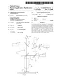
[0015]FIG. 1 schematically describes a microscope system 1 for conducting FCS measurements. The microscope system 1 is provided with at least one first light source 3 which emits illuminating light which is directed onto a sample volume 5 or a sample. Additionally, a target light source 7 for marking the FCS volume 5 is provided. The target light source 7 emits light 6, which is also directed onto the FCS volume. The wavelength of the illuminating light 2 of the first light source 3 differs from the wavelength of the light 6 of the target light source 7. The light 2 from the illuminating light source 3 and the light 6 from the target light source 7 are combined by a combining element 9 to form a common, collinear beam path. In this case, the combining element 9 can be designed to include a beam splitter. Optionally, the combining element 9 can include an AOTF, an AOBS or an AOM. A correcting optics 10 is provided between the target light source 7 and the combining element 9, in order to compensate chromatic aberrations due to the different wavelengths of the light 2 of the first light source 3 and the light 6 of the target light source 7. The light 2 of the first light source 3 and the light 6 of the target light source 7 is directed onto the sample volume 5 or the volume via a plurality of optical elements 12 and a microscope optics 14. The sample volume 5 or sample is preferably provided at least on an X-Y table 16, in order thereby to change the sample volume with respect to the position of the illuminating light. The sample volume 5 is excited to fluoresce due to the illumination by the first light source 3, so that the sample volume 5 emits a detection light 15, which is also directed onto the detector 18 via the microscope optics 14 and the optical elements. The light 6 of the target light source 7 has a longer wavelength than the illuminating light 2 of the first light source 3. In a first embodiment, the light 2 of the target light source 3 has a wavelength lying in the region of red light. The location of the light 6 of the target light source 7 on the sample volume 5 can therefore be observed directly and visually by a user 24. If the light 6 of the target light source 7 lies in the wavelength region of IR light, a camera 22 is provided which produces an image for the user 24, so that the latter can recognize the location of the illuminating light 25 in the sample volume 5.
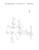
[0016]FIG. 2 shows a further embodiment of the microscope system 1. Arranged downstream of the combining element 9 is an optical fiber 30 into which the illuminating light 2 of the at least first light source 3 and the light 6 of the target light source are coupled. The collinearity of the illuminating light is achieved by coupling the illuminating light 2 of the light 6 of the target light source 7 into the optical fiber 30. This ensures that the light 6 of the target light source 7 and the illuminating light 2 of the at least first light source 3 impinge on a shared impingement location 25 in the sample volume 5 or in the sample. The optical fiber 30 can be provided with a coupling-in optics 31 and a coupling-out optics 32.
User Contributions:
comments("1"); ?> comment_form("1"); ?>Inventors list |
Agents list |
Assignees list |
List by place |
Classification tree browser |
Top 100 Inventors |
Top 100 Agents |
Top 100 Assignees |
Usenet FAQ Index |
Documents |
Other FAQs |
User Contributions:
Comment about this patent or add new information about this topic:
| People who visited this patent also read: | |
| Patent application number | Title |
|---|---|
| 20160350353 | ELIMINATION OF LOG FILE SYNCHRONIZATION DELAY AT TRANSACTION COMMIT TIME |
| 20160350352 | MAINTAINING CROSS-NODE COHERENCE OF AN IN-MEMORY DATABASE OBJECT IN A MULTI-NODE DATABASE CLUSTER |
| 20160350351 | IN-PLACE UPDATES WITH CONCURRENT READS IN A DECOMPOSED STATE |
| 20160350350 | ENSURING THE SAME COMPLETION STATUS FOR TRANSACTIONS AFTER RECOVERY IN A SYNCHRONOUS REPLICATION ENVIRONMENT |
| 20160350349 | DEPENDENT COMMIT QUEUE FOR A DATABASE |
Images included with this patent application:
 |  |
 |
| Similar patent applications: | |
| Date | Title |
|---|---|
| 2014-02-06 | Pump-combining systems and techniques for multicore fiber transmissions |
| 2011-09-29 | Microscope adapter unit |
| 2012-02-02 | Microscope system |
| 2012-04-19 | Microscope system |
| 2012-04-26 | Microscope system |
| New patent applications from these inventors: | |
| Date | Title |
|---|---|
| 2019-09-12 | Illumination apparatus for a microscope |
| 2016-02-18 | Spim arrangement |
| 2016-02-18 | Method and optical arrangement for manipulating and imaging a microscopic sample |
| 2015-11-26 | Spim microscope with a sequential light sheet |
| 2014-10-09 | Arrangement for use in the illumination of a specimen in spim microscopy |
| Top Inventors for class "Optical: systems and elements" | |
| Rank | Inventor's name |
|---|---|
| 1 | Tsung Han Tsai |
| 2 | Hsin Hsuan Huang |
| 3 | Michio Cho |
| 4 | Niall R. Lynam |
| 5 | Tsung-Han Tsai |