Patent application title: Weather insulation barrier
Inventors:
Jimmy D. Bills (Brownwood, TX, US)
IPC8 Class: AE04B200FI
USPC Class:
5250601
Class name: Static structures (e.g., buildings) sheetlike element assembled parallel to existing wall, ceiling, or floor (e.g., insulating panel, sheathing)
Publication date: 2008-12-04
Patent application number: 20080295434
Inventors list |
Agents list |
Assignees list |
List by place |
Classification tree browser |
Top 100 Inventors |
Top 100 Agents |
Top 100 Assignees |
Usenet FAQ Index |
Documents |
Other FAQs |
Patent application title: Weather insulation barrier
Inventors:
Jimmy D. Bills
Agents:
THE INVENTORS NETWORK, INC.
Assignees:
Origin: CARNEGIE, PA US
IPC8 Class: AE04B200FI
USPC Class:
5250601
Abstract:
A weather insulation barrier or block for insulating residential,
commercial, and industrial dwellings and structures includes a
rectangular-shaped panel member that includes a flat backing member to
which an insulation member, preferably composed of foam rubber, is
secured with the insulation member being slightly smaller than the
backing member whereby the backing member defines a continuous peripheral
lip with the long sides of the lip being centered on and secured to
joists or studs that form the framework of a wall or the floor of an
attic thereby providing year-round insulation for the dwelling or
structure. The panel members can also be interconnected to form an
insulation roll whereupon the panel members can be unrolled and used as
needed.Claims:
1. A weather insulation barrier for securement to the joists and studs of
a framework of a structure for insulating the structure, comprising:a
lightweight, portable panel member including:a rectangular-shaped backing
member having an exterior surface and an opposite interior surface;a
rectangular-shaped insulation member attached to the interior surface of
the backing member;the insulation member composed of an insulation foam
material;a protective covering for encasing therein the insulation foam
material;a continuous peripheral flap integrally formed from the backing
member and peripherally extending past the insulation member;the
continuous peripheral flap further defined by having two opposed
short-sided flap portions and two long-sided flap portions; andwhereupon
the panel member is secured to the joists and studs of the framework by
centering the long-sided portions of the flap of the panel member on and
against adjacent joists and studs and then stapling the long-sided
portions of the flap to the joists and studs thereby securing the panel
member to the framework and providing insulation for the dwelling.
2. The weather insulation barrier of claim 1 further comprising a roll of interconnected panel members so that each panel member can be selectively detached from the roll for placement within the framework of the dwelling.
3. A weather insulation barrier for securement to the joists and studs of a framework of a structure for insulating the structure, comprising:a lightweight, portable panel member including:a rectangular-shaped backing member having an interior surface and an opposite exterior surface;a rectangular-shaped insulation member attached to the interior surface of the backing member;the insulation member composed of an insulative foam material;a continuous peripheral flap formed from the backing member and peripherally extending about and past the insulation member;the continuous peripheral flap further defined by having two opposed long-sided flap portions and two opposed short-sided flap portions; andwhereupon the panel member is positioned on the framework and attached thereto by centering the opposed long-sided flap portions of the panel member on and against adjacent joists and studs and then stapling the long-sided flap portions to the joists and studs thereby securing the panel member in position to the framework for insulating the structure.
4. The weather insulation barrier of claim 3 further comprising a roll of panel members with each panel member adjoined to an adjacent panel member along their respective long-sided flap portions so that each panel member can be detached from the roll as needed for insulating the structure.
Description:
FIELD OF THE INVENTION
[0001]The present invention pertains to all-weather insulation materials, and more particularly pertains to a lightweight, portable weather insulation barrier that provides for year-round structural insulation.
BACKGROUND OF THE INVENTION
[0002]The need to conserve energy is an acute concern to members of society from individual homeowners to commercial, industrial, and government agencies, organizations, and institutions. With the primary existing fossil fuels having as many drawbacks as advantages--from the political instabilities of oil-producing countries to the potential technological dangers of the nuclear power--one interim solution is energy conservation. Energy conservation by individual homeowners not only lessens dependence on foreign energy sources, but also has the more immediate effect of producing lower utility costs and bills.
[0003]Residential homes and dwellings dissipate and lose energy and heat in numerous ways. From leaky faucets and spigots and lights left on in rooms when no-one is in the rooms to ignoring thermostat settings and poorly constructed windows, heat is lost, energy is wasted and home utility bills and costs are much higher than need be. One of the primary factors in driving up utility costs is a poorly insulated dwelling. Heat is transferred and lost through the roof, the attic, the walls, and the floor of a dwelling, and such heat transference and lost can be greatly minimized and reduced through proper insulation techniques and materials. Prominent insulation materials include fiberglass batting that comes in rolls and which can be cut to fit between the studs or joists of the framework of the dwelling. However, working with this type of insulation material requires skill and care, as the fiberglass strands are an irritant to the skin and a danger if inhaled. Insulative foam boards are also available but these are placed on the framework of the dwelling as it is being constructed, and it is difficult, if not impossible, to add the insulative boards to a completed dwelling. What is needed is an insulation material that has year-round effectiveness, is easy to install by amateurs as well as professionals, is reasonably priced, and has multiple uses so that the insulation material can insulate pipes, plumbing fixtures, and heaters located not only in the dwelling but in maintenance buildings, sheds, and barns.
[0004]Thus, the prior art discloses a number of materials and forms for insulative blocks and barriers, as well as methods and processes for making the same.
[0005]For example, the Herweg et al. patent (U.S. Pat. No. 3,951,717) discloses a process for making a laminate that includes a foam core formed between two impermeable cover sheets.
[0006]The Koonts patent (U.S. Pat. No. 4,121,958) discloses an insulation board wherein a closed cell foam core is enclosed between a porous fabric or paper sheet with a network of glass strands disposed between the foam core and the paper sheet.
[0007]The Gluck et al. patent (U.S. Pat. No. 4,764,420) discloses a thermally insulating structural laminate having two major surfaces with at least one of the surfaces having an air and water impervious sheet attached thereto.
[0008]The Kelch et al. patent (U.S. Pat. No. 5,695,870) discloses an insulation board that includes an insulating plastic foam material sandwiched between thermoplastic facer films.
[0009]The Ohga et al. patent (U.S. Pat. No. 6,235,806 B1) discloses an open-celled rigid polyurethane foam covered by and in a gas barrier film container with the container being sealed to provide for the vacuum insulation material.
[0010]The LeDuc patent (U.S. Pat. No. 6,613,425 B2) discloses a foam board system and method of making the same that includes a first layer, a second layer, and a central layer encased between the first and second layers.
[0011]The Groft et al. patent application (U.S. patent application publication number US2005/0118408 A1) discloses a multi-layer insulation having an aluminum layer, and a first foam layer positioned on one side of the aluminum layer and a second foam layer positioned on the other side of the aluminum layer.
[0012]Nonetheless, despite the ingenuity of the above devices, systems, and methods of making the same, there remains a need for a low cost, easy to install, effective weather insulation block for homeowners and do-it-yourself home remodelers as well as professional builders and contractors.
SUMMARY OF THE INVENTION
[0013]The present invention comprehends a lightweight, easy-to-install weather insulation barrier or block for use in residential, commercial, and industrial dwellings and structures for keeping the structures and dwellings cool in the summer and preventing heat loss and maintaining the warmth of the dwelling or structure during the colder winter months. Two primary uses of the weather insulation barrier are for placement between the studs of the framework for a room and for placement between the joists that form the floor of a room or between the joists that form the floor of an attic.
[0014]The weather insulation barrier or block of the present invention includes a generally rectangular-shaped panel member sized to fit between studs or joists having 16-inch centers. The panel member includes a rectangular-shaped backing member, preferably of flexible supportive paper, with the backing member including a continuous peripheral lip for attaching the panel member to the joists or studs of the framework of the dwelling or structure. The backing member includes an interior surface and an opposite exterior surface.
[0015]Secured to the interior surface by any conventional means, such as by gluing, is a rectangular-shaped insulation member. The insulation member is preferably composed of foam rubber, and the insulation member has a thickness of at least three and one half inches for providing the desirable amount of insulation as determined by specific R-value ratings. The length and width dimensions of the insulation member are slightly smaller than the length and width dimensions of the backing member thereby allowing the peripheral lip to extend past the insulation member on all sides of the insulation member.
[0016]In order to secure the weather insulation barrier in place the weather insulation barrier is first positioned between two adjacent studs or joists with the portion of the lips forming each long side of the peripheral lip being centered on and resting against the respective adjacent joists or studs. The weather insulation barrier is then secured to the joists or studs by stapling the long sided portions of the peripheral lip to the joists or studs. The weather insulation barrier can come in individual panel members, or the panel members can be interconnected one to another along their long sides for packaging in rolls with nine panel members per roll being a preferred arrangement.
[0017]It is an objective of the present invention to provide a weather insulation barrier that insulates the walls and attics of homes.
[0018]It is another objective of the present invention to provide a weather insulation barrier that provides for year-around weather insulation for both warming and cooling residential, commercial, and industrial dwellings and structures.
[0019]It is yet another objective of the present invention to provide a weather insulation barrier that prevents heat loss during the winter months, keeps the dwelling cool during the summer months, and also provides for noise control.
[0020]It is still yet another objective of the present invention to provide a weather insulation barrier that is easier and safer to handle than fiberglass insulation panels or batting and doesn't present any respiratory problems or hazards.
[0021]Another objective of the present invention is to provide a weather insulation barrier that has additional uses such being used as an insulation blanket around aboveground pipes and plumbing, insulating water heaters, insulating water pump houses, and insulating livestock sheds and barns.
[0022]Yet another objective of the present invention is to provide a weather insulation barrier that can come in separate and individual panels, or may be packaged in a roll of at least nine panels for each roll and unrolled and used as desired.
[0023]Yet still another objective of the present invention is to provide a weather insulation barrier that is more economical to produce and less expensive for consumers.
[0024]Yet still a further objective of the present invention is to provide a weather insulation barrier that can be used to insulate attics, walls, ceilings, and the sub floors and underpinnings of trailers and homes.
[0025]These and other objects, features, and advantages will become apparent by those skilled in the art upon a perusal of the following detailed description read in conjunction with the accompanying drawing figures and appended claims.
BRIEF DESCRIPTION OF THE DRAWINGS
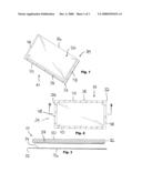
[0026]FIG. 1 is a perspective view of the weather insulation barrier of the present invention illustrating one panel member of the weather insulation barrier;
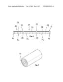
[0027]FIG. 2 is a top plan view of the weather insulation barrier of the present invention illustrating the panel member first shown in FIG. 1;
[0028]FIG. 3 is a sectioned elevational view of the weather insulation barrier of the present invention taken along lines 3-3 of FIG. 2;
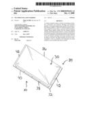
[0029]FIG. 4 is a perspective view of the weather insulation barrier of the present invention illustrating the placement of several insulative panel members within a portion of a framework, and between studs, of a structure;
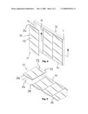
[0030]FIG. 5 is a perspective view of the weather insulation barrier of the present invention illustrating the placement of several insulative panel members between spaced-apart joists that form the floor of an attic of a dwelling;
[0031]FIG. 6 is a sectioned elevational view of the weather insulation barrier of the present invention illustrating the placement of several insulative panel members on the joists that extend across and form the floor of the attic; and
[0032]FIG. 7 is a perspective view of the weather insulation barrier of the present invention illustrating a number of insulative panel members interconnected to form an insulation roll wherein the roll can be unwrapped for removing the individual insulative panel members as needed.
DETAILED DESCRIPTION OF THE PREFERRED EMBODIMENT
[0033]Illustrated in FIGS. 1-7 is an insulative weather barrier or block 10 for providing year round insulation for residential, commercial, and industrial structures and dwellings. The insulative weather barrier 10 is easy to handle and install for both professionals and do-it-yourself amateurs, and is used to insulate the framework--roofs, ceilings, walls, floors, underpinnings and sub floors--of structures, but can also be used to insulate exposed outside and outdoor pipes and plumbing, water pump houses, sheds and barns for livestock, etc.
[0034]As shown in FIGS. 1-7, the weather insulation barrier 10 can be used to insulate the framework of a structure, such as a residential home, for keeping the home cool in the summertime and warm in the wintertime by preventing the loss of heat. For representative purposes FIG. 4 illustrates a portion of a framework 12 for a wall with the framework 12 including four vertically extending studs 14 (three of which are shown) secured at their respective upper ends and lower ends to a bottom piece 16 and a top piece 18. FIGS. 5 and 6 illustrate the weather insulation barrier 10 being used to insulate a portion of an attic 20 that includes a plurality of spaced-apart joists 22 that extend across and form the floor of the attic 20.
[0035]As illustrated in FIGS. 1-7, the weather insulation barrier or block 10 includes a lightweight, portable, easy-to-handle panel member 24. The panel member 24 is generally rectangular-shaped and preferably has the dimensions of 15 inches in width by 94 inches in length. Thus, the panel member 24 is sized to fit between and centered on joists or studs having 16-inch centers. It should be noted that an alternative width of 23 inches would allow the panel member 24 to be attached to joists or studs having 24-inch centers.
[0036]The panel member 24 includes an insulation member 26 that is preferably a foam rubber insulation material 28. The insulation member 26 is preferably three and one half inches thick and is surrounded and encased in and by a thin protective covering 30. The protective covering 30 is water and weather resistant for protecting and maintaining the integrity of the insulation foam material 28. Attached to the insulation member 26, as shown most distinctly in FIG. 3, is a backing member 32 preferably composed of a pliable, water and weather-resistant paper material. The rectangular-shaped backing member 32 includes an interior surface 34 and an opposite exterior surface 36. In addition, when the backing member 32 is permanently secured to the insulation member 26 by any conventional means, such as by gluing, (specifically, the insulation member 26 is secured to the interior surface 34 of the backing member 32), a continuous peripheral lip or flap 38 is formed that extends completely about and circumscribes the insulation member 26. The continuous flap or lip 38 is further defined by having two opposed long-sided flap portions 40 and two opposed short-sided flap portions 42 with the short-sided flap portions 42 being at right angles to the long-sided flap portions 40. Furthermore, the continuous lip or flap 38 is integrally formed because the insulation member 26 has length and breadth dimensions that are less than the backing member 32 thereby allowing for the continuous peripheral extension of the lip 38 out or beyond the body of the insulation member 26. The continuous flap or lip 38 is flexible in order to facilitate its securement to the framework of the dwelling as will be hereinafter further described.
[0037]In addition to the weather insulation barrier 10 comprising individual panel members 24, the weather insulation barrier 10 can come in rolls, as shown the roll 44 in FIG. 7, wherein a plurality of panel members 24 are interconnected in the form of the roll 44 to each other along their respective and adjoined long-sided flap portions 40. A preferred arrangement will include nine panel members 24 to the roll 44, and the panel members 24 can be detached from each other by tearing or separating one panel member 24 from an adjoined panel member 24 along their respective long-sided flap portions 40 as needed for placement in the desired part of the framework of the dwelling for insulation purposes.
[0038]In placing the weather insulation barrier 10 in a part or portion of the framework, such as the framework 12 of the wall as shown in FIG. 4 or the attic floor 20 as shown in FIG. 5, the first step would be to measure the area (length times width) to be insulated. The panel members 24 would then be laid one at a time between the studs 14 or joists 22 so that the long-sided portions 40 of the flaps 38 of two adjacent panel members 24 are centered on the same stud 14 or joist 22 with the long-side portions 40 of both flaps 38 abutting each other and laying against and upon the respective stud 14 or joist 22. The flaps 38 would then be secured to the stud 14 or joist 22 by any convenient means, such as by stapling, and this process would continue until the entire framework was filled with panel members 24, such as is shown by the representative framework 12 of FIG. 4, or until panel members 24 cover the entire attic floor, such as shown by the panel members 24 covering the representative attic floor 20 of FIGS. 5 and 6.
[0039]While embodiments of the weather insulation barrier of the present invention have been shown with regard to specific details, it will be appreciated that numerous alterations, variations, and changes to the present invention can be made while still being fairly within the scope of the invention as set forth by the specification and appended claims.
User Contributions:
comments("1"); ?> comment_form("1"); ?>Inventors list |
Agents list |
Assignees list |
List by place |
Classification tree browser |
Top 100 Inventors |
Top 100 Agents |
Top 100 Assignees |
Usenet FAQ Index |
Documents |
Other FAQs |
User Contributions:
Comment about this patent or add new information about this topic:
Images included with this patent application:
 |  |
 |  |
| Similar patent applications: | |
| Date | Title |
|---|---|
| 2009-06-04 | Weather-resistive barrier for buildings |
| 2012-03-29 | Foam insulation board with edge sealer |
| 2013-02-14 | Attachment member for insulation panel |
| 2010-11-11 | Perimeter insulation strips |
| 2013-03-07 | Solar roof tile with solar and photovoltaic production of hot water and electrical energy |
| New patent applications in this class: | |
| Date | Title |
|---|---|
| 2016-12-29 | Impact damping mat, equipment accessory and flooring system |
| 2016-05-12 | Insulated attic access enclosure |
| 2016-03-17 | Waterproof decorative sheath system for walls of moist environments, and method for making it |
| 2015-12-10 | Method of strengthening existing structures using strengthening fabric having slitting zones |
| 2015-11-12 | Soundproofing panel |
| Top Inventors for class "Static structures (e.g., buildings)" | |
| Rank | Inventor's name |
|---|---|
| 1 | Darko Pervan |
| 2 | Gregory F. Jacobs |
| 3 | Husnu M. Kalkanoglu |
| 4 | Ronald P. Hohmann, Jr. |
| 5 | Mark Cappelle |