Patent application title: Solid state tesla coil suit
Inventors:
Jeffrey Messer (San Bernardino, CA, US)
IPC8 Class: AF41B1504FI
USPC Class:
361232
Class name: Electricity: electrical systems and devices electric charge generating or conducting means (e.g., charging of gases) for application to living beings
Publication date: 2008-11-20
Patent application number: 20080285201
Inventors list |
Agents list |
Assignees list |
List by place |
Classification tree browser |
Top 100 Inventors |
Top 100 Agents |
Top 100 Assignees |
Usenet FAQ Index |
Documents |
Other FAQs |
Patent application title: Solid state tesla coil suit
Inventors:
Jeffrey Messer
Agents:
MILBANK, TWEED, HADLEY & MCCLOY
Assignees:
Origin: NEW YORK, NY US
IPC8 Class: AF41B1504FI
USPC Class:
361232
Abstract:
A wearable suit apparatus incorporating one or more user-operated solid
state tesla coils includes a full body clothing article constructed of
integrated, conductive shielding material. An on board power supply such
as a battery pack powers the one or more solid state tesla coils, which
are connected to the suit such that the entire suit is held at or near
the same potential as the base of the secondary coil(s) of the SSTC(s),
thereby protecting the wearer from injury from the high voltage.Claims:
1. A solid state tesla coil suit apparatus comprising:a full body clothing
article constructed of conductive shielding material;a power supply
carried on said clothing article; andat least one solid state tesla coil
carried on said clothing article and connected to said power supply, said
clothing article connected to the base or ground of said solid state
tesla coil secondary coil so that said clothing article is held at or
near the same potential as the grounded base of the secondary coil.
2. The solid state tesla coil suit apparatus of claim 1 wherein said full body clothing article includes an arm portion, and said at least one solid state tesla coil is carried on said arm portion.
Description:
CROSS REFERENCE TO RELATED APPLICATIONS
[0001]This application claims the benefit of U.S. Provisional Application Ser. No. 60/930,221, filed May 15, 2007; U.S. Provisional Application Ser. No. 60/936,506, filed Jun. 20, 2007; and U.S. Provisional Application Ser. No. 61/004,373, filed Nov. 27, 2007.
STATEMENT REGARDING FEDERALLY SPONSORED RESEARCH OR DEVELOPMENT
[0002]Not applicable.
REFERENCE TO A MICROFICHE APPENDIX
[0003]Not applicable.
TECHNICAL FIELD
[0004]The present invention relates generally to high voltage electronics, and more particularly to an improved wearable suit apparatus incorporating one or more solid state tesla coils.
BACKGROUND INFORMATION AND DISCUSSION OF RELATED ART
[0005]U.S. Pat. No. 4,753,088 to Harrison, et al. discloses mesh knit fabrics having electrically conductive filaments for use in manufacture of anti-static garments and accessories. The open mesh warp knit fabric of the present invention includes a base fabric knit with electrically nonconductive base yarn and forming an open mesh pattern of lightweight construction having spaced openings to provide ventilation therethrough. Electrically conductive filaments are incorporated in the base fabric and provide an open grid extending throughout the entire area of the base fabrics with the conductive filaments being incorporated predominantly in only one side of the base fabric. The conductive yarns provide only about one-half of one percent of the total weight of the fabric and are of a relatively fine denier so that the conductive yarn is substantially invisible to the naked eye. Various types of garments and accessories are illustrated as being formed of the electrostatic dissipating fabric.
[0006]U.S. Pat. No. 5,103,504 to Dordevic describes textile fabric shielding electromagnetic radiation, and clothing made thereof. The textile fabric is made of threads spun of textile fibers, containing cotton, and of steel fibers having a diameter of 6 to 10μm. The number of mixed yarn threads in warp direction and in weft direction each is 18 to 20 threads per cm, and the yarn fineness of the textile fabric is especially 38 to 40 tex. The textile fabric guarantees a shielding of 20 to 40 dB against electromagnetic radiation at a frequency of 10 GHz. The fabric has the quality of usual clothing, and the clothing thereof is designed with respect to proportions, seams, fasteners, and other special features in a manner such that especially people wearing pacemakers, or hospital and radar personnel, are protected against electromagnetic radiation.
[0007]U.S. Pat. No. 5,802,607 to Triplette teaches fencing jackets made from electrically conductive threads. A garment for use in electronically-scored, contact-sports competitions is described. The garment is in the form of a fencing jacket or vest, is substantially wireless, and is woven from electrically conductive threads which cooperate with an electric sports implement to register a score when the implement contacts the electrically conductive garment. The fabric can be woven with the electrically-conductive threads extending in only one of the warp and weft directions, and preferably only in the weft direction.
[0008]U.S. Pat. No. 5,906,004 to Lebby, et al. discloses a textile fabric including a plurality of electrically conductive fibers characterized as providing sufficient current to induce either a wired or wireless coupling between the textile fabric and a portable electronic device. The textile fabric is intended for fabrication into a functional article of clothing or other item made of the woven textile fabric, so as to increase functionality of the article of clothing or item made thereof. The plurality of electrically conductive fibers are characterized as creating an interconnect to a portable electronic device, including integrated components, electronics, or the like, or serving as an antenna for signals received and transmitted by the portable electronic device.
[0009]The foregoing patents reflect the current state of the art of which the present inventor is aware. Reference to, and discussion of, these patents is intended to aid in discharging Applicant's acknowledged duty of candor in disclosing information that may be relevant to the examination of claims to the present invention. However, it is respectfully submitted that none of the above-indicated patents disclose, teach, suggest, show, or otherwise render obvious, either singly or when considered in combination, the invention described and claimed herein.
SUMMARY OF THE INVENTION
[0010]The Solid State Tesla Coil (SSTC) Suit of the present invention provides a wearable suit apparatus incorporating one or more user-operated solid state tesla coils. The inventive apparatus comprises a full body clothing article constructed of integrated, conductive shielding material (e.g. metal mesh pants, jacket, hood, boots, etc.). An on board power supply (such as a DC battery pack) powers the one or more solid state tesla coils, which are connected to the suit such that the entire suit is held at or near the same potential as the base of the secondary coil(s) of the SSTC(s), thereby protecting the wearer from injury from the high voltage.
[0011]The secondary coil(s) and discharge electrode(s) are preferably carried on the arms of the conductive suit, so that the wearer may orient and aim the discharge electrode(s) to direct the sparks (lightning) generated by the coils in any desired direction. In this manner, the inventive suit can be used in applications such as crowd control. The suit also affords the wearer with protection against directed energy weapons.
[0012]In addition to providing adequate conductivity, the inventive conductive clothing preferably also provides flame retardancy, wear resistance, ease of cleaning and maintenance, and wearer acceptance and comfort.
[0013]It is therefore an object of the present invention to provide a new and improved conductive suit.
[0014]It is another object of the present invention to provide a new and improved wearable suit apparatus incorporating one or more user-operated solid state tesla coils.
[0015]Other novel features which are characteristic of the invention, as to organization and method of operation, together with further objects and advantages thereof will be better understood from the following description considered in connection with the accompanying drawings, in which preferred embodiments of the invention are illustrated by way of example. It is to be expressly understood, however, that the drawings are for illustration and description only and are not intended as a definition of the limits of the invention. The various features of novelty which characterize the invention are pointed out with particularity in the claims annexed to and forming part of this disclosure. The invention resides not in any one of these features taken alone, but rather in the particular combination of all of its structures for the functions specified.
[0016]There has thus been broadly outlined the more important features of the invention in order that the detailed description thereof that follows may be better understood, and in order that the present contribution to the art may be better appreciated. There are, of course, additional features of the invention that will be described hereinafter and which will form additional subject matter of the claims appended hereto. Those skilled in the art will appreciate that the conception upon which this disclosure is based readily may be utilized as a basis for the designing of other structures, methods and systems for carrying out the several purposes of the present invention. It is important, therefore, that the claims be regarded as including such equivalent constructions insofar as they do not depart from the spirit and scope of the present invention.
[0017]Further, the purpose of the Abstract is to enable the U.S. Patent and Trademark Office and the public generally, and especially the scientists, engineers and practitioners in the art who are not familiar with patent or legal terms or phraseology, to determine quickly from a cursory inspection the nature and essence of the technical disclosure of the application. The Abstract is neither intended to define the invention of this application, which is measured by the claims, nor is it intended to be limiting as to the scope of the invention in any way.
[0018]Certain terminology and derivations thereof may be used in the following description for convenience in reference only, and will not be limiting. For example, words such as "upward," "downward," "left," and "right" would refer to directions in the drawings to which reference is made unless otherwise stated. Similarly, words such as "inward" and "outward" would refer to directions toward and away from, respectively, the geometric center of a device or area and designated parts thereof. References in the singular tense include the plural, and vice versa, unless otherwise noted.
BRIEF DESCRIPTION OF THE DRAWINGS
[0019]The invention will be better understood and objects other than those set forth above will become apparent when consideration is given to the following detailed description thereof. Such description makes reference to the annexed drawings wherein:
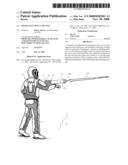
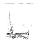
[0020]FIG. 1 is a schematic view of a solid state tesla coil suit apparatus of this invention.
DETAILED DESCRIPTION OF THE INVENTION
[0021]Referring to FIG. 1, there is illustrated therein a new and improved solid state tesla coil suit apparatus, generally denominated 10 herein.
[0022]The inventive apparatus 10 comprises a full body clothing article 11 constructed of integrated, conductive shielding material (e.g. metal mesh pants, jacket, hood, boots, etc.). An on board power supply such as a DC battery pack 12 provides DC power to the high frequency bridge 15 for the primary coil 13 of one or more solid state tesla coils 14 carried on the suit 10. The tesla coil(s) 14 are connected to the suit 10 such that the entire suit is held at or near the same potential as the grounded base 16 of the secondary coil(s) 18 of the SSTC(s), at or near ground level.
[0023]The secondary coil(s) 18 and their respective discharge electrode(s) 18a are preferably carried on the arms of the conductive suit 10, so that the wearer may orient and aim the discharge electrode(s) 18a to direct the sparks (lightning) 20 generated by the coils in any desired direction.
[0024]The above disclosure is sufficient to enable one of ordinary skill in the art to practice the invention, and provides the best mode of practicing the invention presently contemplated by the inventor. While there is provided herein a full and complete disclosure of the preferred embodiments of this invention, it is not desired to limit the invention to the exact construction, dimensional relationships, and operation shown and described. Various modifications, alternative constructions, changes and equivalents will readily occur to those skilled in the art and may be employed, as suitable, without departing from the true spirit and scope of the invention. Such changes might involve alternative materials, components, structural arrangements, sizes, shapes, forms, functions, operational features or the like.
[0025]Therefore, the above description and illustrations should not be construed as limiting the scope of the invention, which is defined by the appended claims.
User Contributions:
comments("1"); ?> comment_form("1"); ?>Inventors list |
Agents list |
Assignees list |
List by place |
Classification tree browser |
Top 100 Inventors |
Top 100 Agents |
Top 100 Assignees |
Usenet FAQ Index |
Documents |
Other FAQs |
User Contributions:
Comment about this patent or add new information about this topic:
Images included with this patent application:
 |  |
| Similar patent applications: | |
| Date | Title |
|---|---|
| 2011-02-17 | Solid state data storage assembly |
| 2012-04-26 | Laminated substrate with coils |
| 2010-01-07 | Solid insulated bus switchgear |
| 2013-05-30 | Method and apparatus for scalable low latency solid state drive interface |
| 2013-08-08 | Pressurised gas-insulated multi-phase control panel |
| New patent applications in this class: | |
| Date | Title |
|---|---|
| 2022-05-05 | Methods and apparatus for a conducted electrical weapon |
| 2016-03-10 | A smartphone electroshock facility |
| 2016-01-14 | Electrode for electronic weaponry that dissipates kinetic energy |
| 2016-01-14 | Electrode for electronic weaponry that dissipates kinetic energy |
| 2015-12-24 | T.o.u.c.h. |
| New patent applications from these inventors: | |
| Date | Title |
|---|---|
| 2008-11-20 | System and method for forming and controlling electric arcs |
| 2008-11-20 | System and method for controlling an electromagnetic field generator |
| Top Inventors for class "Electricity: electrical systems and devices" | |
| Rank | Inventor's name |
|---|---|
| 1 | Zheng-Heng Sun |
| 2 | Levi A. Campbell |
| 3 | Li-Ping Chen |
| 4 | Robert E. Simons |
| 5 | Richard C. Chu |