Patent application title: CALIBRATION OF A PARTIALLY SYMMETRIC FIXTURE
Inventors:
Kan Tan (Beaverton, OR, US)
Assignees:
TEKTRONIX, INC.
IPC8 Class: AG01R3500FI
USPC Class:
702 85
Class name: Data processing: measuring, calibrating, or testing calibration or correction system
Publication date: 2008-11-13
Patent application number: 20080281542
Inventors list |
Agents list |
Assignees list |
List by place |
Classification tree browser |
Top 100 Inventors |
Top 100 Agents |
Top 100 Assignees |
Usenet FAQ Index |
Documents |
Other FAQs |
Patent application title: CALIBRATION OF A PARTIALLY SYMMETRIC FIXTURE
Inventors:
Kan TAN
Agents:
THOMAS F. LENIHAN;TEKTRONIX, INC.
Assignees:
TEKTRONIX, INC.
Origin: BEAVERTON, OR US
IPC8 Class: AG01R3500FI
USPC Class:
702 85
Abstract:
A method useful for the characterization of a fixture splits a partially
symmetric THRU structure into portions which may then be mathematically
removed from both ports of a 2-port measured structure, leaving only the
desired device under test (DUT).Claims:
1. A method for characterizing a partially symmetrical test fixture,
comprising the steps of:providing a partially symmetrical test
fixture;assigning a partial symmetric constraint of
Sx22=Sy11;assigning a designation x to one portion of said test
fixture and a designation y to the remainder of said test fixture for
computation purposes;obtaining S-parameters Sf11, Sf12, and
Sf22 of said test fixture through two port measurements using a
Vector Network Analyzer (VNA) or a Time Domain Reflectometer
(TDR);obtaining S-parameters Sx11 and Sy22 through two port
measurements using a time domain gating method;solving for Sx22 by
applying .+-. ( Sf 11 - Sx 11 ) ( Sf 22 - Sy 22 )
Sf 12 2 ;solving for Sx12 by applying .+-. ( Sf 11 -
Sx 11 ) ( 1 - Sx 22 2 ) Sx 22 ; andsolving for
Sy12 by applying .+-. ( Sf 22 - Sy 22 ) ( 1 - Sx 22
2 ) Sx 22 .
2. A method for characterizing a partially symmetrical test fixture, comprising the steps of:providing a partially symmetrical test fixture;assigning a partial symmetric constraint of Sx22=Sy11;assigning a designation x to one portion of said test fixture and a designation y to the remainder of said test fixture for computation purposes;obtaining S-parameters Sf11, Sf12, and Sf22 of said test fixture through two port measurements using a Vector Network Analyzer (VNA) or a Time Domain Reflectometer (TDR);obtaining S-parameters Sx11 and Sy22 through two port measurements using a time domain gating method;solving for Sx22 by applying .+-. ( Sf 11 - Sx 11 ) ( Sf 22 - Sy 22 ) Sf 12 2 ;wherein when Sx22is equal to zero and THRU traces of said fixture are symmetric then Sx12Sy12=Sf12 and Sx12=Sy.sub.12.
3. A method for characterizing a partially symmetrical test fixture, comprising the steps of:providing a partially symmetrical test fixture;assigning a designation x to one portion of said test fixture and a designation y to the remainder of said test fixture, and a designation f to the entire test fixture for computational purposes;assigning a partial symmetric constraint of Sx22=Sy11;obtaining S-parameters Sf11, Sf12, and Sf22 of said test fixture through two port measurements using a Vector Network Analyzer (VNA) or a Time Domain Reflectometer (TDR);obtaining S-parameters Sx11 and Sy22 through two port measurements using a time domain gating method;solving for Sx22 by applying .+-. ( Sf 11 - Sx 11 ) ( Sf 22 - Sy 22 ) Sf 12 2 ;wherein when Sx22 is equal to zero and THRU traces of said fixture are uniform, then using the ratio between the physical length of the trace on x side and the physical length of the trace on y side to establish the relationship between Sx12 and SY.sub.12.
4. The method of claim 3, wherein the step of using the physical length of the traces to establish the relationship between Sx12 and Sy12 includes a case in which said traces on said x portion of said test fixture are twice as long as said traces on said y side of said test fixture, then Sx12 and Sy12 exhibit a relationship of Sx12=Sy12Sy12; andwhen such relation between Sx12 and Sy12 is established based on said length ratio, thensolving for Sx12 and Sy12 by use of Sx12Sy12=Sf.sub.12.
Description:
CROSS REFERENCE TO RELATED APPLICATIONS
[0001]The subject application claims priority from U.S. Provisional Patent Application Ser. No. 60/916,872, entitled, CALIBRATION OF A PARTIALLY SYMMETRIC FIXTURE (Kan Tan.), filed 09 May 2007, the entire contents of which are herein incorporated by reference.
FIELD OF THE INVENTION
[0002]The subject application concerns, in general, the field of test and measurement instruments, and in particular, concerns characterizing partially symmetric test fixtures.
BACKGROUND OF THE INVENTION
[0003]PCT patent application serial number PCT/US07/75485, CALIBRATION OF A MIRROR-SYMMETRIC FIXTURE (Doubrava, et al.) (hereinafter Doubrava '485), herein incorporated by reference, introduces a method for the characterization of a symmetric fixture, hereinafter called SymmetriCal. The SymmetriCal method (Doubrava '485) splits a symmetric THRU structure into mirrored Half-fixtures which may then be mathematically removed from both ports of a 2-port measured structure, leaving only the probe (i.e., the desired device under test (DUT)). What is needed is a method that can handle partially-symmetric fixtures.
SUMMARY OF THE INVENTION
[0004]A partial symmetric fixture is characterized with a single 2-port S-parameter measurement. The mathematical process splits the fixture into two partially symmetric half-fixtures, completely describing each half in terms of 2-port S-parameters.
BRIEF DESCRIPTION OF THE DRAWING
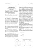
[0005]FIG. 1 shows an example of a partially symmetric fixture.
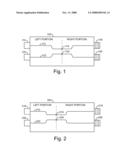
[0006]FIG. 2 shows another example of a partially symmetric fixture.
DETAILED DESCRIPTION OF THE EMBODIMENTS
[0007]The subject invention is an enhanced method which can handle partially symmetric fixtures. One example of partially symmetric fixture 100 is shown in FIG. 1, where the fixture is mostly symmetric, except for the inter-connectors 110, 120 and 116, 126 which are of two different types. The different connectors at the two sides may facilitate the through (THROU) calibration. Test fixture 100 includes a first trace 112 extending from a first connector 110 through a connection pad 114 to a second connector 116, and a second trace 122 extending from a third connector 120 through a second connection pad 124 to a fourth connector 126.
[0008]The second example of partially symmetric fixture 200 is shown in FIG. 2, where the fixture is less symmetric than the one in FIG. 1. Elements in FIG. 2 bearing similar reference numerals to those of FIG. 1 serve the same purpose, and need not be described again. In FIG. 2, only the connection pads 214, 224 and their neighboring area are symmetric.
[0009]The extended method of the subject invention, called Partial SymmetriCal, can handle fixtures satisfying the partial symmetry requirement. The term "partial symmetry", as used herein means that the junction section between two half sides (LEFT and RIGHT Portions) is symmetric.
[0010]The pad areas shown in FIG. 1 and FIG. 2 are symmetric, so the test fixtures in FIG. 1 and FIG. 2 satisfy partial symmetry requirements. But they are not completely symmetric as required by Doubrava '485 (i.e., SymmetriCal®).
[0011]Less strict requirements in accordance with the method of the subject invention (which may be called, Partial SymmetriCal) provide more flexibility for fixture designs. For test fixtures that are supposed to be symmetric, the Partial SymmetriCal provides a means to check how good the symmetry assumption is.
Calibration of Partially Symmetric Fixtures
[0012]A partial symmetric fixture is characterized with a single 2-port S-parameter measurement. The mathematical process splits the fixture into two partially symmetric half-fixtures, completely describing each half in terms of 2-port S-parameters.
[0013]Measurement of a device under test (DUT) embedded between the half-fixtures can be easily de-embedded using the Half-fixture
[0014]S-parameters, or equivalently, T-parameters.
[0015]The partially symmetric fixture F and its components X and Y can be characterized in terms of S-parameters:
Sx = ( Sx 11 Sx 12 Sx 21 Sx 22 ) Sy = ( Sy 11 Sy 12 Sy 21 Sy 22 ) Sf = ( Sf 11 Sf 12 Sf 21 Sf 22 )
TABLE-US-00001
[0016]The partial symmetric constraints is reflected in the model as
Sx22=Sy11 (1)
[0017]The reciprocity constraints applied to each component X, Y as well as whole fixture F yields:
Sx12=SX21
Sy12=SY21
Sf12=Sf21 (2)
[0018]The S-parameters of X, Y and F are related by
[ Sf 11 Sf 12 Sf 21 Sf 22 ] = [ Sx 11 + Sx 12 Sy 11 Sx 21 1 - Sx 22 Sy 11 Sx 12 Sy 12 1 - Sx 22 Sy 11 Sy 21 Sx 21 1 - Sx 22 Sy 11 Sy 22 + Sy 21 Sx 22 Sy 12 1 - Sx 22 Sy 11 ] ( 3 )
[0019]In the equation (3), Sf11, Sf12, Sf22 can be obtained through two port measurements using a Vector Network Analyzer (VNA) or a Time Domain Reflectometer (TDR) on the whole fixture F; Sx11 and Sy22 can be obtained using the time domain gating method described in Doubrava '489.
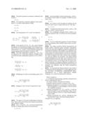
[0020]Only three independent variables Sx12, Sy12, Sx22 are unknown in (3). These three unknown variables can be resolved from three independent equations in (3) as following,
Sx 12 Sy 11 Sx 21 1 - Sx 22 Sy 11 = Sf 11 - Sx 11 ( 4 ) Sx 12 Sy 12 1 - Sx 22 Sy 11 = Sf 12 ( 5 ) Sy 21 Sx 22 Sy 12 1 - Sx 22 Sy 11 = Sf 22 - Sy 22 ( 6 )
[0021]Multiplying (4) with (6) and dividing square of (5) yields
Sx 22 = ± ( Sf 11 - Sx 11 ) ( Sf 22 - Sy 22 ) Sf 12 2 ( 7 )
[0022]Plugging (7) into (4) and (6) respectively to get
Sx 12 = ± ( Sf 11 - Sx 11 ) ( 1 - Sx 22 2 ) Sx 22 ( 8 ) Sy 12 = ± ( Sf 22 - Sy 22 ) ( 1 - Sx 22 2 ) Sx 22 ( 9 )
[0023]The signs in (7) (8) and (9) affect phase of S parameters. They can be resolved from time domain measurement and continuity of phase.
[0024]If Sx22=0, then Sx12, Sy12 can not be computed from (8) and (9). Instead, they need to be resolved from
Sx12SY12=Sf12 (10)
[0025]Extra knowledge of relation between Sx12 and Sy12 are needed to resolve them: for example, if THRU are symmetric, then
Sx12=SY12
[0026]Or, if traces on left and right are uniform, but the trace in X side is twice as long as the trace in Y side, then
Sx12=Sy12Sy12
[0027]Combining the relation between Sx12 and Sy12 with (10), Sx12 and Sy12 can be resolved.
[0028]For a completely symmetric fixture, which is considered in Doubrava '485, (1) will have two extra symmetric terms
Sx12=Sy12
Sx11=Sy22
[0029]It can be verified that equations (3)-(10) with these two extra symmetric terms yield the same results as in Doubrava '485.
[0030]The subject invention (Partial SymmetriCal) can handle fixtures satisfying partial symmetry requirement, which is less strict than completely symmetric required by the SymmetriCal (Doubrava '485) method. For completely symmetric fixture, the Partial SymmetriCal yields the same result as SymmetriCal. For fixtures that are very close to symmetric, the Partial SymmetriCal provides a check on how symmetry it is, and can calibrate out asymmetry. The subject method (Partial SymmetriCal) is the super set of SymmetriCal; the Partial SymmetriCal involves more steps to gain more accurate calibration results. For the fixtures that are almost completely symmetric, if calibration efficiency is preferred over accuracy, then the SymmetriCal should be used; if accuracy is preferred over efficiency, then the Partial SymmetriCal should be used.
[0031]It is noted that the subject invention is also useful in combination with the teaching of U.S. patent application Ser. No. 12/117461 CALIBRATED S-PARAMETER MEASUREMENTS OF A HIGH IMPEDANCE PROBE (Hagerup, et al.), herein incorporated by reference.
User Contributions:
comments("1"); ?> comment_form("1"); ?>Inventors list |
Agents list |
Assignees list |
List by place |
Classification tree browser |
Top 100 Inventors |
Top 100 Agents |
Top 100 Assignees |
Usenet FAQ Index |
Documents |
Other FAQs |
User Contributions:
Comment about this patent or add new information about this topic:
Images included with this patent application:
 |  |
 |  |
 |
| Similar patent applications: | |
| Date | Title |
|---|---|
| 2014-05-29 | Calibration apparatus |
| 2012-06-21 | Calibration arrangement |
| 2013-04-25 | Calibrating breathalyzer |
| 2013-10-24 | Calibrating breathalyzer |
| 2012-07-05 | Method for calibrating oscilloscopes |
| New patent applications in this class: | |
| Date | Title |
|---|---|
| 2019-05-16 | Bird's-eye view image generating device for vessel, and calibration method of the same |
| 2016-07-14 | Measurement system optimization for x-ray based metrology |
| 2016-06-30 | Methods and systems for early signal attenuation detection and processing |
| 2016-06-16 | System and method for on-site measurement apparatus calibration |
| 2016-05-05 | Improved method of signal processing and system including the same |
| New patent applications from these inventors: | |
| Date | Title |
|---|---|
| 2010-04-08 | Equalization simulator with training sequence detection for an oscilloscope |
| 2008-09-25 | Bandwidth multiplication for a test and measurement instrument using non-periodic functions for mixing |
| Top Inventors for class "Data processing: measuring, calibrating, or testing" | |
| Rank | Inventor's name |
|---|---|
| 1 | Lowell L. Wood, Jr. |
| 2 | Roderick A. Hyde |
| 3 | Shelten Gee Jao Yuen |
| 4 | James Park |
| 5 | Chih-Kuang Chang |