Patent application title: Dust-cleaning apparatus for tracking ball
Inventors:
Shu-Feng Lu (Taipei City, TW)
IPC8 Class: AA47L2500FI
USPC Class:
15208
Class name: Brushing, scrubbing, and general cleaning implements fabric
Publication date: 2008-11-13
Patent application number: 20080276399
Inventors list |
Agents list |
Assignees list |
List by place |
Classification tree browser |
Top 100 Inventors |
Top 100 Agents |
Top 100 Assignees |
Usenet FAQ Index |
Documents |
Other FAQs |
Patent application title: Dust-cleaning apparatus for tracking ball
Inventors:
Shu-Feng Lu
Agents:
ROSENBERG, KLEIN & LEE
Assignees:
Origin: ELLICOTT CITY, MD US
IPC8 Class: AA47L2500FI
USPC Class:
15208
Abstract:
A dust-cleaning apparatus for a tracking ball includes a cover, a seat
body, a tracking ball, and a dust-cleaning textile. The tracking ball
rolls inside the seat body that is combined with the cover. Furthermore,
a partially spherical surface of the tracking ball is exposed out of the
seat body. The dust-cleaning textile is disposed between the seat body
and the cover and has a hole for the tracking ball to pass through and
compactly contact the dust-cleaning textile. Due to the compact
contacting with the tracking ball, the dust-cleaning textile prevents
foreign matter from attaching on to the spherical surface of tracking
ball or from entering the seat body. Moreover, foreign matter is isolated
outside the seat body so that the tracking ball can be used normally.Claims:
1. A dust-cleaning apparatus for a tracking ball, comprising:a cover,
having a through-hole;a seat body, combining with the cover and having a
receiving space;a tracking ball, rotatably mounted in the receiving space
of the seat body, and a partially spherical surface of the tracking ball
protruding out of the through-hole of the cover; anda dust-cleaning
textile, located between the cover and the seat body and having a hole
for the tracking ball to pass through and contact the dust-cleaning
textile;wherein the tracking ball has a predetermined relative chord
length greater than or equal to a diameter of the hole in a position
where the tracking ball contacts the dust-cleaning textile so that the
dust-cleaning textile contacts the spherical surface of the tracking
ball.
2. The dust-cleaning apparatus for a tracking ball as claimed in claim 1, wherein the dust-cleaning textile is fixed between the cover and the seat body via adhesion.
3. The dust-cleaning apparatus for a tracking ball as claimed in claim 1, wherein the dust-cleaning textile has locating holes, and fixing tenons are disposed between the cover and the seat body, and the fixing tenons pass through the locating holes to attach the dust-cleaning textile between the cover and the seat body.
4. The dust-cleaning apparatus for a tracking ball as claimed in claim 1, wherein the dust-cleaning textile is made by stacking at least one layer of non-woven fabrics.
5. The dust-cleaning apparatus for a tracking ball as claimed in claim 1, wherein the dust-cleaning textile is made by stacking at least one layer of paper.
6. The dust-cleaning apparatus for a tracking ball as claimed in claim 1, wherein the dust-cleaning textile is made by stacking a plurality of layers of non-woven fabrics and paper.
7. The dust-cleaning apparatus for a tracking ball as claimed in claim 1, further comprising:a circuit board;a light source generator, electrically mounted on the circuit board;a light source detector, electrically mounted on the circuit board;an optical base, mounted on the circuit board, corresponding to a direction along which the light source generator emits light, the light source detector being mounted on a bottom of the optical base, and the seat body sheathing the optical base; anda holding base, mounting a plurality of ball bearings inside thereof, wherein partial surfaces of each ball bearing are exposed out of the holding base, the holding base is disposed in the receiving space of the seat body, and each ball bearing contacts the spherical surface of the tracking ball for locating the tracking ball above the light source generator.
8. The dust-cleaning apparatus for a tracking ball as claimed in claim 7, wherein the seat body is a sleeve.
9. The dust-cleaning apparatus for a tracking ball as claimed in claim 7, wherein the seat body has an opening for a part of the light source generator to pass through, and the holding base has a perforating hole for light emitted from the light source generator to pass through.
10. The dust-cleaning apparatus for a tracking ball as claimed in claim 1, further comprising:a circuit board;two grating wheels, turnably assembled inside the seat body relative to the tracking ball, wherein the tracking ball jointly drives the two grating wheel to rotate; andtwo encoding assemblies, electrically mounted on the circuit board;wherein the seat body is mounted on the circuit board and the two grating wheels correspond to the two encoding assemblies, respectively.
11. The dust-cleaning apparatus for a tracking ball as claimed in claim 10, wherein the seat body integratedly forms the receiving room concavely downwards from an upper surface thereof.
12. The dust-cleaning apparatus for a tracking ball as claimed in claim 10, wherein each of the two encoding assemblies includes a light detector and an encoding circuit.
13. The dust-cleaning apparatus for a tracking ball as claimed in claim 10, wherein each of the two encoding assemblies includes a light transmitter and a light receiver.
Description:
BACKGROUND OF THE INVENTION
[0001]1. Field of the Invention
[0002]The present invention relates to a tracking ball apparatus, and more especially to a dust-cleaning apparatus for a tracking ball which prevents foreign matter from entering.
[0003]2. Description of the Prior Art
[0004]Conventional desktop computers or notebook computers control cursors to move on computer screens via a mouse or a tracking ball apparatus. Taking a prior mechanical mouse as an example, the mechanical mouse disposes two corresponding grating wheels inside a body, and drives the two grating wheels to turn via a tracking ball, it then works out variation signals of light projected on to a light detector through the grating wheels via an encoding circuit, thereby detecting the direction of the movement of the tracking ball and further synchronously controlling the position of the cursor on the computer screen.
[0005]Secondly, taking prior tracking ball apparatuses as an example, tracking balls are provided in some devices, such as a keyboard or the shell of a notebook computer, or are connected to a host computer via USB, etc. Users can turn the tracking balls with their hand and synchronously control the position of the cursor on the computer screen via controlling movements of the tracking ball.
[0006]There are usually two types of prior tracking ball apparatuses, the first is a mechanical tracking ball apparatus which has the same structure as the above mechanical mouse and works on the same principles; the second type is an optical tracking ball apparatus. The optical tracking ball apparatus uses a light source generator (such as a laser diode, etc.) to emit light on a spherical surface of a tracking ball. The light is reflected to show an interference fringe pattern. Then, the interference fringe pattern on the spherical surface of the tracking ball is detected by an optical detector, which thereby works out the direction and distance of the movement of the tracking ball and synchronously controls the position of the cursor on the computer screen.
[0007]However, regardless of whether the tracking ball apparatus is a mechanical tracking ball apparatus or an optical tracking ball apparatus, the tracking ball is disposed on the upper surface of the mouse (alternatively, the tracking ball of the mouse can be disposed on the lower surface of the mouse), so foreign matter (such as dust, pieces of food, and so on) on the fingers of users is easily attached to the spherical surface of the tracking ball which then enters the tracking ball apparatus. Also, foreign matter can directly enter the tracking ball apparatus from outside. When the apparatus is used over a long period, foreign matter easily accumulates inside the tracking ball apparatus. Taking an optical tracking ball apparatus as an example, foreign matter covers the optical detector so that eventually the optical detector can no longer accurately detect the spherical surface of the tracking ball, which causes the tracking ball apparatus to be unable to control the cursor precisely. Given a long enough period of time, the apparatus may eventually become damaged itself.
[0008]Accordingly, for improving the above shortcomings, several conventional ways are provided as described below:
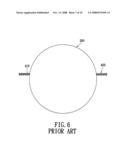
[0009]1. As shown in FIG. 6, a film 400 (such as a piece of polyester resin) with a hole 410 is disposed in a tracking ball apparatus. A tracking ball 300 passes through the hole 410. Foreign matter on a spherical surface of the tracking ball 300 is removed or isolated via scraping.
[0010]2. As shown in FIG. 7, a conventional cloth 500 made of long fibers is disposed inside the tracking ball apparatus, and foreign matter on the spherical surface of the tracking ball 300 is removed or isolated via friction.
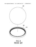
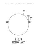
[0011]3. As shown in FIGS. 8 and 9, a brush 600 is disposed inside the tracking ball apparatus, and foreign matter on the spherical surface of the tracking ball 300 is removed via brushing.
[0012]However, though conventional tracking ball apparatus can remove foreign matter via the above conventional methods, tracking ball apparatuses still have shortcomings as are described below:
[0013]1. Using the film 400 to scrape. When the chord length of the tracking ball 300 is greater than or equal to a diameter of the hole 410, the friction caused by using the tracking ball 300 increases so that the tracking ball 300 cannot operate normally. When the chord length of the tracking ball 300 is less than the diameter of the hole 410, removal and isolation of foreign matter is negatively affected.
[0014]2. Using the cloth 500 made of long fibers. The cloth 500 is too thick and long fibers inside and outside the tracking ball 300 move jointly so that friction caused by using the tracking ball 300 increases and the tracking ball 300 cannot operate normally. Furthermore, the whole structure is too thick, which makes the design of the tracking ball apparatus more difficult.
[0015]3. The method of using the brush 600 is limited due to the density of the bristles 610 of the brush 600. If the bristles 610 of the brush 600 have lower density, the brush 600 cannot remove foreign matter or prevent foreign matter from entering. If the bristles 610 of the brush 600 have higher density, the entire structure of the tracking ball apparatus is too thick and friction caused by using the tracking ball 300 increases.
[0016]Hence, the inventors of the present invention believe that the shortcomings described above are able to be improved upon and suggest the present invention as being of a reasonable design and as an effective improvement based on deep research and thought.
SUMMARY OF THE INVENTION
[0017]An object of the present invention is to provide a dust-cleaning apparatus for a tracking ball which prevents foreign matter from directly entering the apparatus thereby preventing the components inside the apparatus from being affected by foreign matter and ensuring that the apparatus can be used normally. The present invention reduces friction and ensures that the structure does not become too thick.
[0018]To achieve the above-mentioned object, a dust-cleaning apparatus for a tracking ball in accordance with the present invention is disclosed. The dust-cleaning apparatus for a tracking ball includes a cover having a through-hole; a seat body combined with the cover and having a receiving space; a tracking ball rotatably mounted in the receiving space of the seat body, wherein the partially spherical surface of the tracking ball protrudes out through the through-hole of the cover; and a dust-cleaning textile of one or more than one layer of elements made from non-woven fabrics or/and paper, wherein the dust-cleaning textile is located between the cover and the seat body and has a hole through in which the tracking ball contacts the dust-cleaning textile.
[0019]The tracking ball has a relative chord length slightly greater than or equal to a diameter of the hole in a position where the tracking ball contacts the dust-cleaning textile so that the dust-cleaning textile contacts the spherical surface of the tracking ball.
[0020]The efficacy of the present invention is as follows: depending on the dust-cleaning textile compactly contacting the tracking ball, the present invention prevents foreign matter from becoming attached to the spherical surface of the tracking ball or from entering the seat body. Moreover, the foreign matter is isolated outside the seat body to avoid components inside the seat body from being affected by foreign matter so that the tracking ball can be used normally. Secondly, the present invention has a dust-cleaning textile made of non-woven fabrics or/and paper, which has the characteristics of being made using short fibers and is light and short, thereby reducing friction and ensuring that the structure does not become too thick.
[0021]To further understand features and technical contents of the present invention, please refer to the following detailed description and drawings related the present invention. However, the drawings are only to be used as references and explanations, not to limit the present invention.
BRIEF DESCRIPTION OF THE DRAWINGS
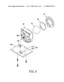
[0022]FIG. 1 is an exploded perspective view of the present invention;
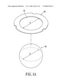
[0023]FIG. 1A is a detailed view of part A of FIG. 1;
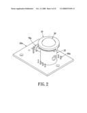
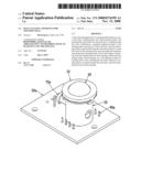
[0024]FIG. 2 is an assembled perspective view of the present invention;
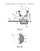
[0025]FIG. 3 is a sectional plan view of the present invention;
[0026]FIG. 3A is a detailed view of part A of FIG. 3;
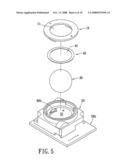
[0027]FIG. 4 is an exploded perspective view of another embodiment of the present invention;
[0028]FIG. 5 is a partially exploded perspective view of another embodiment of the present invention;
[0029]FIG. 6 is a sketched view of a combination of a tracking ball and a film in a prior tracking ball apparatus;
[0030]FIG. 7 is a sketched view of a combination of the tracking ball and cloth in the prior tracking ball apparatus;
[0031]FIG. 8 is a sketched view of a combination of the tracking ball and a brush in the prior tracking ball apparatus; and
[0032]FIG. 9 is another sketched view of the combination of the tracking ball and the brush in the prior tracking ball apparatus.
DETAILED DESCRIPTION OF THE INVENTION
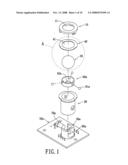
[0033]Please refer to FIGS. 1-3, in which a dust-cleaning apparatus for a tracking ball in accordance with a preferred embodiment of the present invention is shown. The dust-cleaning apparatus for a tracking ball includes a cover 10, a seat body 20, a tracking ball 30, and a dust-cleaning textile 40.
[0034]The cover 10 forms a through-hole 11 in a center thereof. The seat body 20 forms a receiving space 21 therein, and the tracking ball 30 can be rotatably mounted in the receiving space 21. The dust-cleaning textile 40 has at least one layer of elements made of non-woven fabrics or/and paper, such as at least one layer of elements which are made by non-woven fabrics stacked upon one another in turn, or at least one layer of elements which are made of paper stacked upon one another in turn, or a plurality of layers of elements which are made of non-woven fabric and paper stacked upon one another in turn. The non-woven fabric are for example made of PP (Polypropylene) and the paper can be Xuan paper or other similar such kinds of paper having the characteristics of short fibers. The dust-cleaning textile 40 has a hole 41 in a center thereof, which has a diameter d (as shown in FIG. A).
[0035]To assembly the apparatus, the dust-cleaning textile 40 is disposed on an upper surface of the seat body 20 so that the tracking ball 30 can pass through the hole 41. Furthermore, a spherical surface of the tracking ball 30 can contact the dust-cleaning textile 40. Next, the cover 10 and the seat body 20 combine with each other by fastening, locking, or other means. The partially spherical surface on a top of the tracking ball 30 protrudes upwards from the through-hole 11 of the cover 10 and out of the cover 10. The combination of the seat body 20 and the cover 10 ensures that the dust-cleaning textile 40 can be located between the cover 10 and the seat body 20.
[0036]Furthermore, for improving the stability of the dust-cleaning textile 40, the dust-cleaning textile 40 is fixed between the cover 10 and the seat body 20 by adhesion, such as adhesion provided by double-sided tape or glue. Alternatively, the dust-cleaning textile 40 can be fixed between the cover 10 and the seat body 20 by fastening. For example, the dust-cleaning textile 40 can form a plurality of locating holes (not shown) around the hole 41 which, and a plurality of fixing tenons (not shown) corresponding to the locating holes are disposed between the cover 10 and the seat body 20. The fixing tenons can protrude upwards from the upper surface of the seat body 20. Alternatively, the fixing tenons can also protrude downwards from a lower surface of the cover 10. The fixing tenons pass through the locating holes so as to fix the dust-cleaning textile 40 between the cover 10 and the seat body 20.
[0037]Furthermore, it is worth mentioning that the present invention can be used in optical structures or mechanical structures. As shown in FIGS. 1-3, taking an optical structure as an example, the present invention can further include a circuit board 50a, a holding base 60a, a light source generator 70a, a light source detector 80a, and an optical base 90a. The seat body 20 is a sleeve with two openings at both ends. The seat body 20 forms a receiving room 21 thereinside and an opening 22 on a side edge thereof (as shown in FIG. 3). A plurality of ball bearings 61a which can roll are mounted inside the holding base 60a. The partial surfaces of each ball bearing 61a are exposed out of the holding base 60a. A perforating hole 62a is formed in a center of the holding base 60a. The light source generator 70a is electrically mounted on the circuit board 50a. The optical base 90a is mounted on the circuit board circuit 50a and corresponds to the direction along which the light source generator 70a emits light. The light source detector 80a is disposed on a bottom of the optical base 90a and electrically connects to the circuit board 50a.
[0038]To assembly the apparatus, the seat body 20 sheaths the optical base 90a firstly so that a front portion of the light source generator 70a passes through the opening 22 of the seat body 20 and corresponds to the optical base 90a. The holding base 60a is mounted inside the receiving space 21 of the seat body 20 and is located on the optical base 90a. Next, the tracking ball 30 is disposed inside the receiving space 21 of the seat body 20. Each ball bearing 61a of the holding base 60a contacts the spherical surface on a bottom of the tracking ball 30 to locate the tracking ball 30 above the light source generator 70a. After that, the dust-cleaning textile 40 and the cover 10 are assembled in turn.
[0039]Please refer to FIG. 1A and FIG. 3A. The relative chord length D (also known as the section diameter) of any portion of the tracking ball 30 is slightly greater than or equal to (i.e. not less than) a diameter of the hole 41 of the dust-cleaning textile 40. Thereby the dust-cleaning textile 40 can compactly contact the spherical surface of the tracking ball 30. In other words, the diameter d of the hole 41 is determined by the chord length D of the tracking ball 30 wherein the dust-cleaning textile 41 contacts the tracking ball 30 and must be slightly less than or equal to the chord length D of the tracking ball 30 in this position, to avoid the dust-cleaning textile 40 from contacting the spherical surface of the tracking ball 30 and thereby losing efficacy in removing dust.
[0040]Additionally, in the present invention, the dust-cleaning textile 40 is made of non-woven fabrics or/and paper so the dust-cleaning textile 40 has the characteristics of having short fibers and is light-weighted and small-sized. The dust-cleaning textile 40 can adjust the number of the layers depending on actual demand to have one layer or a plurality of layers of non-woven fabrics or paper or a combination of stacked non-woven fabrics and paper (in FIG. 3A, taking one layer as an example), thereby adjusting the friction between the dust-cleaning textile 40 and the tracking ball 30 and avoiding the friction from becoming too great that it affects the operation of the tracking ball 30. The dust-cleaning textile 40 is light-weighted and small-sized, and thereby avoids the whole structure from becoming too thick. However, when users roll or turn the tracking ball 30, there is an exerting force position. Because the non-woven fabrics or/and paper are short fibers, the short fibers inside/outside the tracking ball 30 are unable to move jointly. As such, users only need to exert a small amount of force on the exerting force position to easily roll/turn the tracking ball 30.
[0041]Light from the light source generator 70a can be emitted to the optical base 90a and reflected by the optical base 90a to pass through the perforating hole 62a of the holding base 60a. The light is then projected on to the spherical surface of the tracking ball 30. The light source detector 80a can detect the light projected on the spherical surface of the tracking ball 30 through the optical base 90a and the perforating hole 62a, and then work out the direction and distance of the movement of the tracking ball 30 to obtain displacement data, thereby controlling the position of the cursor on the computer screen.
[0042]As shown in FIG. 4 and FIG. 5, an embodiment with mechanical structures can further include a circuit board 50b, two grating wheels 60b, and two encoding assemblies 70b. The above seat body 20 integratedly forms a receiving room 21 concavely downwards from the upper surface to directly receive the tracking ball 30. The two grating wheels 60b are turnably assembled inside the seat body 20, relative to the tracking ball 30. The tracking ball 30 can jointly drive the two grating wheels 60b to turn. The two encoding assemblies 70b are electrically disposed on the circuit board 50b. Each of the two encoding assemblies 70b includes a light detector 71b and an encoding circuit 72b. Alternatively, each encoding assembly 70b can include a light transmitter and a light receiver. In the figures of the present invention, the light detector 71b and the encoding circuit 72b are taken as examples.
[0043]To assembly the apparatus, the seat body 20 is directly mounted on the circuit board 50b via screws to make the two grating wheels 60b correspond to the two encoding assemblies 70b respectively. Next, the tracking ball 30, the dust-cleaning textile 40, and the cover 10 are assembled in turn. When turning, the tracking ball 30 drives the two grating wheels 60b to turn at the same time. The encoding circuit 72b of the encoding assembly 70b works out the variation signals of light projected on to the light detector 71b via the grating wheels 60b to detect the direction and position of the movement of the tracking ball 30. Alternatively, when the encoding assembly 70b includes a light transmitter and a light receiver, the grating wheels 60b have a plurality of light holes through which light from the light transmitter is received by the light receiver. Accordingly, when the grating wheels 60b are turning, a decoding circuit can be obtained to work out variations in the light projected on to the light receiver through the light hole for obtaining the displacement data, thereby controlling the position of the cursor on the computer screen.
[0044]Based upon the above description, the dust-cleaning textile 40 can compactly contact the tracking ball 30 to effectively prevent foreign matter from becoming attached on the spherical surface of the tracking ball 30 or from entering the seat body 20. Moreover, foreign matter is isolated outside the seat body 20 to avoid the components inside the seat body 20 (such as the light source detector 80a, the encoding assembly 70b, and so on) from being affected by accumulated foreign matter so that the mouse can not operate normally, which affects the precise operation of the cursor, and avoids damage from being caused to the components inside the seat body 20. Secondly, the present invention uses the dust-cleaning textile 40 made of non-woven fabrics or/and paper, which have the characteristics of short fibers and is light-weighted and short-sized, thereby reducing friction and avoiding the structure from becoming too thick, thereby improving upon the shortcomings of the prior art.
[0045]What is disclosed above is only the preferred embodiment of the present invention and it is therefore not intended that the present invention be limited to the particular embodiments disclosed. It will be understood by those skilled in the art that various equivalent changes may be made depending on the specification and the drawings of present invention without departing from the scope of the present invention.
User Contributions:
comments("1"); ?> comment_form("1"); ?>Inventors list |
Agents list |
Assignees list |
List by place |
Classification tree browser |
Top 100 Inventors |
Top 100 Agents |
Top 100 Assignees |
Usenet FAQ Index |
Documents |
Other FAQs |
User Contributions:
Comment about this patent or add new information about this topic:
| People who visited this patent also read: | |
| Patent application number | Title |
|---|---|
| 20090303851 | Method And Apparatus For Reproducing Data And Recording Medium |
| 20090303850 | OPTICAL DISC MEDIUM AND OPTICAL DISC DEVICE |
| 20090303849 | OPTICAL PICKUP DEVICE AND RECORDING/REPRODUCTION DEVICE |
| 20090303848 | OPTICAL DISCS WITH IDENTIFICATION CODE |
| 20090303844 | OPTICAL PICKUP AND DISK DRIVE DEVICE |
Images included with this patent application:
 |  |
 |  |
 |  |
 |  |
 |  |
 |
| Similar patent applications: | |
| Date | Title |
|---|---|
| 2009-08-06 | Dust collection apparatus for demolition tool |
| 2010-10-14 | Cleaning apparatus for escalator rails |
| 2010-11-25 | Cleaning apparatus for solar panels |
| 2010-06-10 | Cleaning apparatus for large diameter pipe |
| 2011-06-16 | Cleaning apparatus and cleaning method for wafer |
| New patent applications in this class: | |
| Date | Title |
|---|---|
| 2013-10-17 | Cleaning cloth |
| 2011-09-29 | Cleaning device |
| 2010-12-09 | Device for cleaning the oral cavity |
| 2010-10-21 | Myriad pad |
| 2009-01-22 | Multi-phase hygienic cleansing system and skin care device |
| New patent applications from these inventors: | |
| Date | Title |
|---|---|
| 2009-05-07 | Optical image detecting structure with multiple function |
| Top Inventors for class "Brushing, scrubbing, and general cleaning" | |
| Rank | Inventor's name |
|---|---|
| 1 | Wayne Ernest Conrad |
| 2 | Xavier Boland |
| 3 | Helmut Depondt |
| 4 | Robert Moskovich |
| 5 | James Dyson |